2717
Technical Committee 212 /
Comité technique 212
elements is independent of the mesh representing soil (so called
embedded piles). Bearing capacity of the pile base is modelled
by equivalent force. Its value is calculated based on the stress
state and bearing capacity of a soil at the level of pile base.
Schemes of plane strain and three dimensional models are
shown in Figs. 3 and 4.
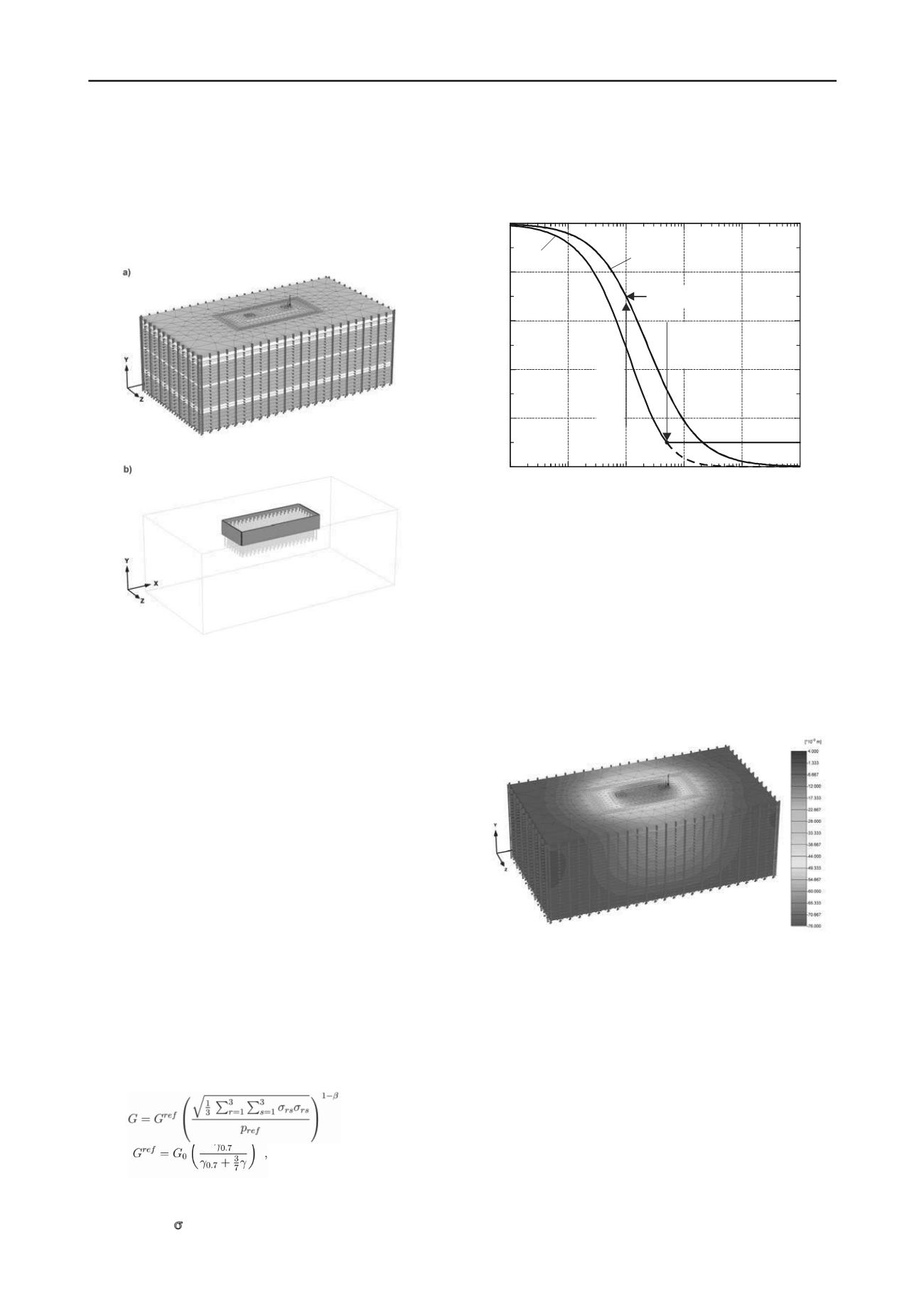
Figure. 4: 3D FEM mesh of foundation model: a) general view with
boundary conditions, b) detail of pile elements (so called embedded
piles) and sheet pile wall elements (plate elements). Foundation body
modelled by continuum elements.
The main goal of the last calculation stage was a
determination of the subsoil resistance and an assessment of the
foundation settlements during the construction phase as well as
during its operation. Besides strength of the soil layers which
was modelled by either Coulomb-Mohr or Matsuoka-Nakai
strength criteria, special attention was paid to possibly accurate
description of the soil stiffness. For that purpose non-linear
stiffness model including description of small strain behaviour
of soil was adopted. Conventional implementation of constant
stiffness with secant parameters (Table 1) leads to unrealistic
overestimations of the settlements in majority of practical cases
of raft foundations. It is well known from the laboratory and in
situ investigations that the stiffness increase with the mean
effective stress, however on the other hand it degrades due to
accumulation of large shear strains (Atkinson, 2000), (Santos
and Correia, 2000). The nonlinear small strain stiffness was
included in the model for fine grained soils. Small strain
stiffness moduli for the soil layers were determined in the
triaxial tests equipped with bender elements, (report (2), 2008).
The value of current shear modulus
G
was calculated
according to the following formulas:
(1)
(2)
where
G
and
G
ref
are current and reference tangent shear moduli
respectively,
G
ref
=
E
ref
/(2(1-
)) at mean reference stress
p
ref
= 200 kPa;
is the stress tensor;
= 0.5 is power parameter
expressing the dependence of the stiffness on effective stress
and
0.7
is shear strain at which shear modulus
G
ref
decreases
about 30% with respect to
G
0
– initial modulus at reference
stress
p
ref
(see Fig. 5).
G
[kPa ]
G
0
/ [-]
10
-1
10
1
10
0
10
2
10
3
10
-2
G
t
min
G G
s
=0.7
0
G
s
G
t
/ =1.0
co
/
0.7
Figure 5: Dependence of shear modulus on shear strains.
G
t
=
G
ref
and
G
s
are tangent and secant shear moduli, respectively and
G
tmin
is a
minimal shear modulus at the accumulation of shear strain
co
.
The calculation results show that for estimated strength
parameters of the soil layers stability of the foundation is
preserved. In the numerical simulations the foundation was
stable even for doubled loads. Minimum factor of safety for the
foundation model received by
-
c
reduction method was
F
= 1.35. The uniform settlement of the foundation was 0.08 m,
whereas maximum settlement difference was 0.01 m.
Exemplary distribution of vertical displacements for the
calculation scheme assuming maximum horizontal loads has
been shown in Fig. 6.
Figure. 6: Distribution of vertical displacement obtained for
maximum lateral load calculation scheme.


