2716
Proceedings of the 18
th
International Conference on Soil Mechanics and Geotechnical Engineering, Paris 2013
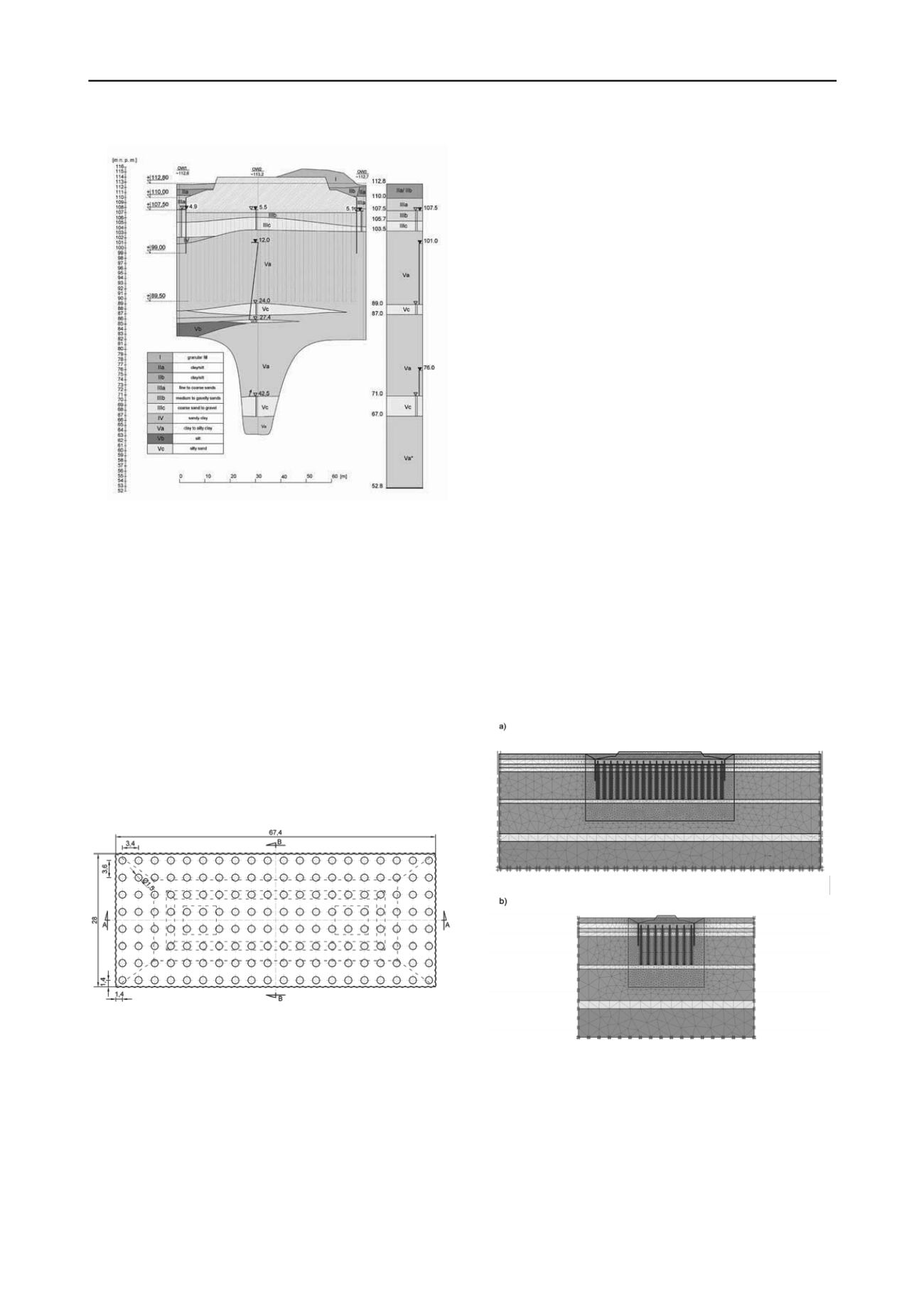
Figure 1: Characteristic geotechnical cross-section with the
simplified system of layers.
3
TECHNOLOGICAL SOLUTION OF THE FOUNDATION
Four alternatives regarding the foundation of the pylon were
being considered i.e.: shallow foundation in the layer of dense
coarse soils, foundation on the diaphragm walls, foundation on
the block made of jet-grouting columns and foundation on large
diameter bored piles. Finally, the latest concept has been
assumed for design. Additionally bored piles were strengthened
by the injection under the pile base. Such solution was found to
be optimal technologically in the soil conditions. The concept of
shallow foundation was rejected due to small thickness of
coarse material below the foundation level. In the case of
diaphragm walls the problem might be low shaft bearing
capacity. The foundation on the block made of injection
columns has been rejected due to large volume and mass of the
block.
Figure 2: Projection of the foundation with the lay-out of pile heads.
The foundation foot has size of 67.4 m x 28.0 m and is
founded on 160 large diameter bored piles. The piles have a
rigid connection with the slab. The piles of diameter
D
=150 cm
and length of 18 m are spaced in the rectangular grid
3.4 m x 3.6 m, (Fig. 2). The bottom of the foundation slab is
localized at the elevation of 107.5 m a.s.l. and rests on the 0.5 m
thick layer of blinding concrete. The perimeter of the foundation
foot was protected by sheet pile wall of the length of 11.0 m
(between elevations of 99 m to 110 m a.s.l.). The sheet pile wall
is not a foundation element transmitting the loads into the
subsoil but it is used as erosion protection.
The lack of high strength soil layer, did not allow to design
base bearing piles, hence the raft foundation system was
designed. In such system transmission of loads takes place both
by piles as well as by foundation slab. The main layers deciding
of bearing capacity and settlements of the foundation are layers
of over-consolidated tertiary clays No. Va and Vc. The base
level of the piles is designed in the upper part of geotechnical
layer No. Va above the confined aquifer Vc. The confined
aquifer is not considered as weak layer from the strength point
of view, nevertheless it should be protected against any
perforation due to high water pressure occurring in it. It was
recommended to concrete the piles by dry method however this
recommendation could not be fully achieved. The piles have
been strengthen by injection under their bases. During the
injection both grout pressure and pile heave were controlled.
4
CALCULATIONS
At the preliminary stage of the foundation design several
schemes of pile foundation system were analyzed. In the
simplest scheme no direct soil - foundation slab interaction as
well as infinite stiffness of slab were assumed (rigid foundation
method). Here, maximal compression force in pile was
estimated at the level of 7200 kN for the envelope of maximum
moments acting at the top of foundations, whereas minimum
compression force was 5300 kN. In the next calculation stage
the foundation was analysed as boundary-value problem solved
by finite element method. The discretization was based on
structural elements such as shells and beams resting on elastic
supports. The characteristics of elastic supports have been
calculated based on the stiffness of soil layers. The soil response
under the slab was assumed as uniform passive ground pressure
equal to 100 kPa. It allowed to assess the values of internal
forces in the foundation slab and in the piles. These forces were
necessary for design of the reinforcement. The maximum
calculated axial force in the pile was 7367 kN and meets
standard bearing capacity condition just on the edge of safety
whereas maximum bending moment was 4742 kNm.
Figure 3: Foundation model with FEM mesh in plane strain state: a)
longitudinal section, b) cross-section. Piles and sheet pile walls are
modeled by beam elements with averaged stiffness.
Final calculation stage regarded numerical simulation of
boundary-value problem by finite element method with
discretization of the foundation body and geotechnical layers by
continuum elements. The piles were discretised by beam
elements directly interacting with soil elements. Calculations
were carried out for simplified schemes in plane strain state
with averaging stiffness of piles in rows and in the complex
three dimensional model. In the later case alignment of beam


