3302
Proceedings of the 18
th
International Conference on Soil Mechanics and Geotechnical Engineering, Paris 2013
deformation of dam body and the deformation of concrete face
slab.
2.1
Deformation coordination standards
1
)
Coordination standard of dam body settlement
I
y y
S S
i
i
i
i
1
1
(
1
)
I
x x
S S
i
i
i
i
1
1
(
2
)
where
S
i
and
S
i
+1
are settlement at
i
point and
i
+1 point of
dam body (cm);
y
i
and
y
i
+1
are coordinate at
i
point and
i
+1
point at direction of stream(m);
x
i
and
x
i
+1
are coordinate at
i
point and
i
+1 point at direction of dam axis(m); [
I
] is limit of
inclination(the difference of settlement)
2
)
Coordination standard of dam body horizontal
displacement
T
y y
D D
i
i
Byi
Byi
1
1
(
3
)
T
x x
D D
i
i
Bxi
Bxi
1
1
(
4
)
where
D
Byi
and
D
Byi
+1
are horizontal displacement at stream
direction at
i
point and
i
+1 point of dam body(cm);
D
Bxi
and
D
Bxi
+1
are horizontal displacement at dam axis direction at
i
point and
i
+1 point of dam body(cm); [
T
] is limit of
displacement difference.
3)
Coordination synchronously between dam body
deformation and concrete face slab deformation
] [
)
(
max
s
j fi
j Bfi
H
d
D
(
5
)
][
)
(
max
J
d
D
j xi
j
Bxi
(
6
)
)
, , ,
/1(
] [
f t f E f
H
y f t
c
s
(
7
)
)
, , , , /1( ][
f
y f c c
Cf t f E f
J
(
8
)
Where
j Bfi
is displacement of dam body
i
point at normal
direction of face slab at
j
time(cm);
D
j fi
d
is deflection of face
slab
i
point at
j
time(cm);
j
Bxi
is displacement of dam body
i
point at dam axis direction or at direction of face slab slope at
j
time(cm);
D
j xi
d
is displacement of face slab
i
point at dam axis
direction or at direction of face slab slope at
j
time(cm); [
H
s
] is
limit of separation height of face slab(cm); [
J
] is limit of
displacement difference between dam body and face slab at
dam axis direction or at face slab slope direction(cm).
E
c
is
elastic modulus of concrete;
f
c
is compressive strength of
concrete;
f
t
is tensile strength of concrete;
t
f
is thickness of
concrete face slab;
f
y
is compressive strength or tensile strength
of reinforcement;
C
f
is
friction coefficient between face slab
and cushion layer.
2.2
Deformation coordination judgment criteria
The above-mentioned deformation coordination judgment
criteria including [
I
], [
T
], [
H
s
] and [
J
] depend on the physical
and mechanical properties of dam filling material and concrete,
the dimension of face slab, as well as stress condition of dam
body and concrete face slab. The above-mentioned judgment
criteria could be decided by laboratory tests or back analysis
based on prototype observation data. The laboratory tests
include large scale simple shear test, large scale triaxial
compression or extension test and large scale contact surface
test. The real or modified material is used as dam filling
material and face slab concrete in laboratory tests. The stress
condition of sample in the test should imitate the real stress
condition of dam body or face slab during construction or
operation.
The prototype observation data from Tianshengqiao No.1
Dam, Aguamilpa Dam, Campos Noves Dam, Barra Grande
Dam, Mohale Dam and Shuibuya Dam could be used to analyze
the reasons for causing the above-mentioned serious damages.
The above-mentioned judgment criteria also could be
obtained from back analysis.
2.3
Calculation method and contact surface constitutive
relation
A three-dimensional finite element method (FEM) could be
used as deformation coordination calculation method. NHRI
(Nanjing Hydraulic Research Institute) double yield surface
elastic-plastic model and Duncan E-B non-linear elastic model
could be used to modeling dam filling material. A contact
surface damage constitutive model could be used to modeling
contact surface performance as the following formula.
i
n
n
a
n
w I
e
P
P
P
K
e
e
n
aP
n n
n
a
n n
n
a
n n
tan
1
2
2
1
2
1
2
1
n
d
n
e
P
e
P
c
e
e
n
Pa
n n
n
a
n n
n
aP
n n
n
a
n n
tan
2
1
2
1
2
1
2
1
(9)
Where
τ
is shear stress of contact surface;
σ
n
is normal stress
of contact surface;
γ
is shear strain of contact surface; Pa is a
standard atmospheric pressure;
α
、
i
、
d
、
C
n
、
K
1
、
n
、
n
1
、
n
2
are model parameters. The model parameters of two
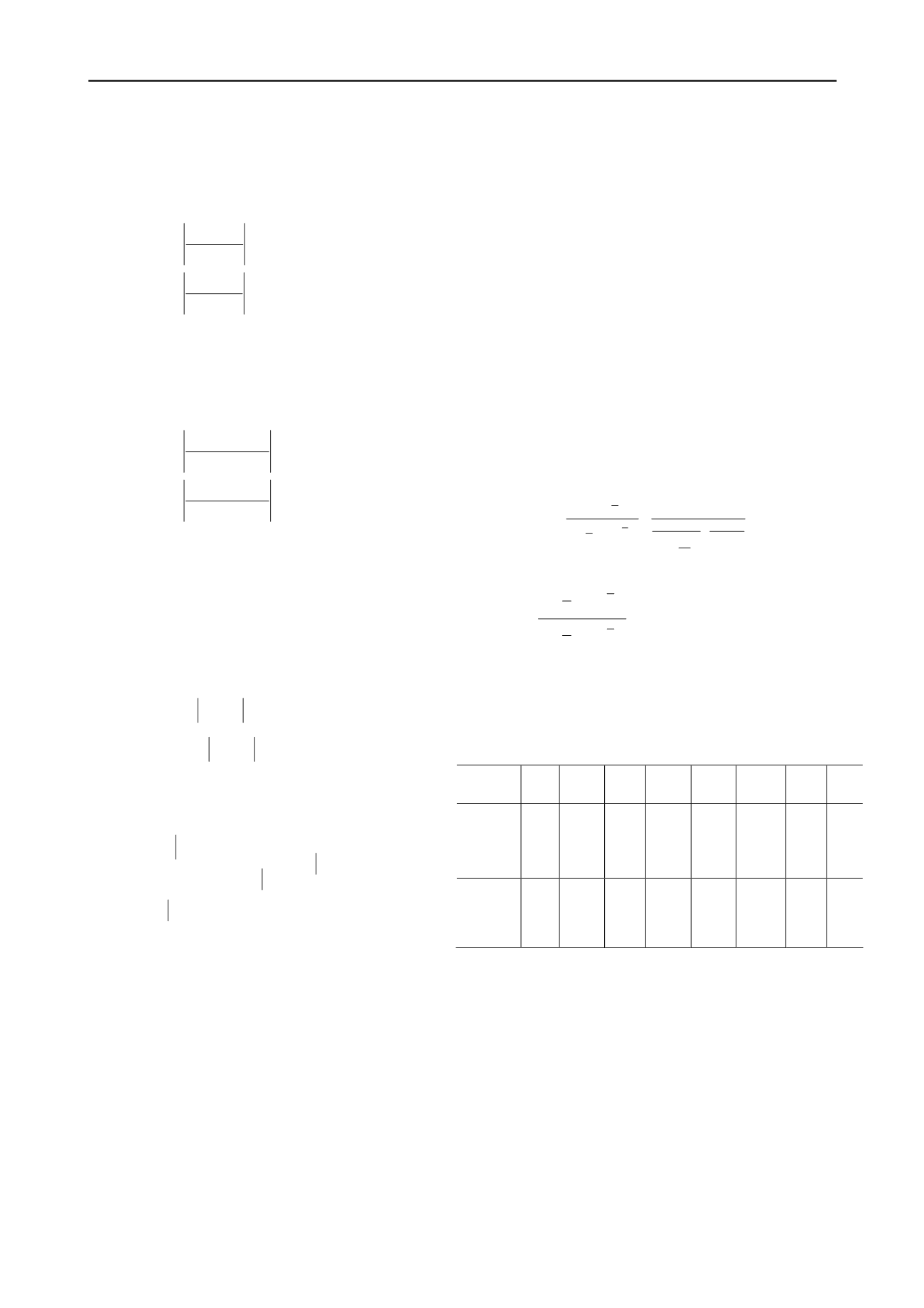
typical CFRDs are shown in Table 1 Table 1. Parameters of
contact surface damage constitutive model
Dam
name
K
1
n
i
d
C
n
α
n
1
n
2
Houz
iyan
(223.
5m high)
2
3
0.
49
1
.2
0.
50
5.
42
0.
040
2
.0
-
0.9
5
Jinch
uan
(112
m high)
2
0
0.
55
1
.2
0.
47
2.
02
0.
045
1
.6
-
0.3
4
The effectiveness of fitting the contact surface damage
constitutive model to contact surface test results for Houziyan
Dam is quite good as shown in Figure 1.


