3299
Technical Committee 210 + 201 /
Comité technique 210 + 201
where soil loosening effect may occur. It can cause the change
of filtration factor and flow of water perpendicular to the
surface of the model which is impossible to capture in 2D
modelling.
The calculation results of phreatic level in Variant 4 are
presented on Drawing 10. This variant was based on the
assumption that there is piping effect and hypothetically
watertight facing in the area of slope with reinforcing concrete
panels. In calculations the position of phreatic level is different
from what was observed in nature.
3
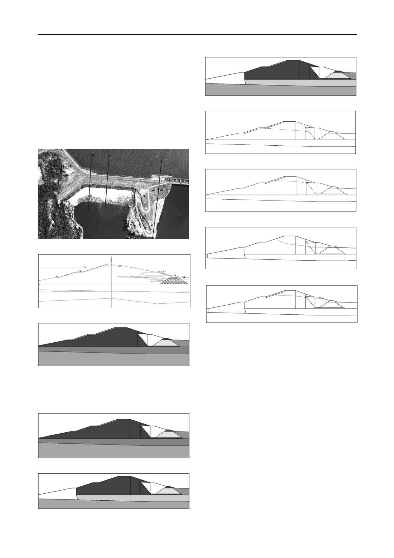
DRAWINGS
Drawing 1 Earth dam location plan showing the orientation of cross-
section taken for calculations
Drawing 2 Cross-section V with low density material zones marked
Drawing 3 Variant 1 Material zones scheme – location of the insulation
at upstream slope
Material description – 1) dam drainage 2) impermeable layer 3) dam body – fine
sand 4) loose zone within dam body 5) concrete panels/facing covering upstream
slope of the dam 6) sands 7) berm 8)vertical piping – see drawings 5&6. 9)horizontal
piping – see drawings 5&6 a) locations of piezometers taken into account for model
establishment.
Drawing 4 – Variant 2 Material zones scheme – location of the
insulation at upstream slope, within zone of concrete panels
Drawing 5 Variant 3 Material zones scheme – piping effect at dam base
Drawing 6 Variant 4 Material zones scheme – piping effect at dam base
plus watertight facing within zone of concrete panels installation
Drawing 7 Variant 1 Phreatic level across earth dam and material zones
Drawing 8 Varian 2 Phreatic level across earth dam and material zones.
Drawing 9 Variant 3 Phreatic level across earth dam and material zones
Drawing 10 Variant 4 Phreatic level across earth dam and material
zones
a 3
a
4a
1
7
8
9
2
5
a
4
3
a
a
1
7
6
4
CONCLUSIONS
The observed phreatic level course within the earth dam
body differs significantly from the design values, which were
assumed based on specified, stable downstream water level.
In Variant 3 the location of piping failure has been assumed
based on known oxbow presence or base loosening indicated
during the last phase of earth dam construction. These locations
are hypothetical, however low phreatic level within dam body
proves that phenomenon hazardous to Włocławek Dam exists.
In Variant 4, both of piping failure existence and parallel
reinforcing of concrete panels at upstream slope induce
deterioration of earth dam working conditions within the
drainage zone (where interface between drainage and dam
material not exists). It causes flow concentration and rising of
the phreatic level and thus further development of suffusion
phenomenon within ends of filtration paths through the dam.
Further, the seepage deformation might develop without
strictly and immediately visible symptoms, and therefore might
not be noticed during the operational activity of the entire
structure.
This shall be also concluded, that construction of new dam,
below the existing Włocławek Dam should improve its working
conditions by reducing the differences between up- and
downstream water levels, and thus pressure gradients which
cause the suffusion within and below dam body.
2
5
3
4
a
a
a
7
1
6
2
a
3
4
a
a
1
7
8
9
2
5


