3291
Technical Committee 210 + 201 /
Comité technique 210 + 201
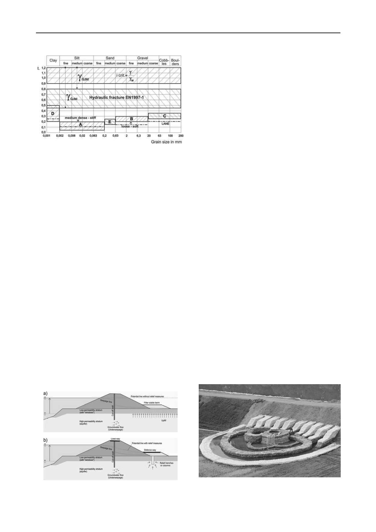
Figure 3. Critical hydraulic gradients for hydraulic fracture (internal
erosion) (Brandl and Hofmann, 2006); i
crit.
depends not only on grain
size distribution and density/stiffness but also on flow pressure;
G,dst
=
partial safety factor for permanently unfavourable effects.
used increasingly since the early 1970s. Common filter criteria
for soils are from Terzaghi and Sherard, and for geotextiles
from Giroud (2010) and Heibaum et al (2006). All criteria have
particular limitations, whereby non-cohesive and cohesive soils
have to be distinguished. While two criteria are sufficient for
granular filters (the permeability criterion and the retention
criterion), four criteria are required for geotextile filters (Giroud
2010): the porosity criterion and the thickness criterion also
have to be considered.
3 MAESURES AGAINST HYDRAULIC FAILURE
Hydraulic failure as an effect of underseepage may be
prevented mainly by two permanent measures landward of a
dyke or flood protection dam by
installing trenches or relief columns or drainage wells,
filling of berms, thus displacing the possible starting point
of inner erosion or piping further away from the structure,
and decreasing the hydraulic gradient at this point. Such
berms should be constructed as access roads for quick and
easy dam defence in the case of severe floods.
The function of the berm is to compensate through its
counterweight the pressure which is acting at the base of the
cover layer (Fig. 4a) and to prevent hydraulic failure of the dyke
by seepage or uplift, or by internal erosion and piping. At the
same time it must allow a free water outflow. Otherwise an
excessive pore-water pressure would cause a sudden failure.
Filter stable berms (filter geotextiles covered with sand, gravel,
or other granular material) are often used as an emergency
measure, when seepage occurs.
In many cases berms merely move the hydraulic
problem further away from the dyke or dam, and retrogressive
inner erosion may finally reach it in the long term (after several
Figure 4. Permanent measures against hydraulic failure caused by
underseepage of flood protection dykes: a) Filter stable berm as a
counterweight; b) Relief drainage columns or trenches.
floods). Boiling and internal erosion have been observed up to
20 to 50 m away from dykes and dams, even though they were
only 3 to 6 m high (Fig. 3). Moreover, wide berms are
frequently not possible under confined space condition as well
as in ecological sensible areas along rivers; therefore drainage
trenches are preferred in these circumstances.
However, trenches excavated in very soft soil collapse
immediately before geotextiles and fill material can be placed.
The installation of trussed retaining panels would be too
expensive. These problems could be overcome by developing
‘relief granular columns’, jacketed with a filter geotextile.
Jacketed (coated) stone or gravel columns have been
installed in Austria since 1992. At first they were used mainly
for drainage purposes, for instance as drainage walls to improve
the stability of old flood protection earth dams. This method has
significant construction advantages over conventional drainage
trenches in loose or soft soil. In critical cases the coated
columns are combined with other measures for dam
refurbishment. The drainage material (usually clean 4/32 mm,
8/32 mm or 16/32 mm grain) is lowered by vibroflotation,
whereby the vibrator is wrapped with a nonwoven geotextile
(tied together at the toe of the vibrator).
The tops of relief columns should be covered with
coarse drainage material, wrapped in filter geotextiles for
longitudinal or transverse drainage. This drainage layer should
carry an access road for easy dam defence in the case of severe
floods.
Relief columns or trenches are filter stable elements at
the landside embankment toe integrated into the dyke profile to
reduce the pressure at the base of the low permeable cover layer
during the critical flood stages (Fig. 4b). The safety factor
against hydraulic failure (erosion or heaving) significantly
increases through the controlled pressure relief. The negative
effect of this measure is the concentrated groundwater outflow.
This can lead under certain hydraulic gradients, soil/subgrade
conditions and local topography to an earlier waterlogging of
the hinterland.
Figure 4b illustrates also the typical cross-section
through a new flood protection dyke after removal of the old
one, which had been destroyed by a severe flood. The coated
gravel columns (diameter 0.7 m) usually exhibit a spacing
between 1.5 and 7.0 m, depending on local factors (geotechnical
and ecological parameters, infrastructure, risk potential etc.);
spacing is commonly about 4 m. The water-side dam slope is
covered by a net for protection against beavers.
Another method to increase the stability against inner
erosion is to reduce the hydraulic gradient by raising the water
level at the landside in local reservoirs (Fig. 5). This method
represents an emergency measure by placing sandbags around
the erosion crack and is often used after indication of local
hydraulic fracture in the beginning stage.
Figure 5. The giant piping at Tiszhasa/Hungary in 2000 and stabilizing
measures (Nagy, 2011): Reduction of hydraulic gradient and lateral
support of dyke slope.


