3282
Proceedings of the 18
th
International Conference on Soil Mechanics and Geotechnical Engineering, Paris 2013
2.1 Flow erosion of overtopping
When dike is not high enough to flood water level, overtopping
will be happened. As most of the dikes are constructed by earth
material, soil erosion by the flow of overtopping could cause the
failure of the dike. Although no papers in ISSMGE 2013 have
discussed this issue, it is still an important problem in dike
engineering. In recently years, some overtopping cases were
occurred and have finally led to the failure of the dikes. The
dikes failure by Hurricane Katrina in 2005 in New Orleans,
Louisiana, USA and Mississippi River levee failures by 2008
flood in USA are the typical cases of overtopping dike failure.
With occurrence of overtopping, the flow will erode the
downstream side of the dike. Normally, soil erosion starts from
the downstream toe of the dike, then develops upward to dike
crest and finally lend to dike breach. The degree of damage
depends on the depth and duration of overtopping as well as the
soil properties. For geotechnical engineers, the more concerned
issue is the impacts of soil properties on the flow erosion of
overtopping. The overall index is the erodibility of the soil.
For the soils of dike, most of them are cohesive soil, the
erodibility depends on its physic and mechanical properties,
which include plasticity, water content, grain size, percent clay,
compaction, and shear strength. In the study of soil erosion,
Briaud has developed a method to determine the erosion
function of a given soil (Briaud 2008). Based on this method,
Michelle B. (2011) has conducted detailed investigation on the
overtopping failure of Mississippi levee in the flood of June
2008 in USA. The studies have presented the levee overtopping
case of the Winfield-Pin Oak site that was overtopped and
severe erosion led to failure, and the Brevator site that was also
overtopped but did not fail. By using Erosion Function
Apparatus (EFA) (Briaud 2008), soil properties of plasticity
index (PI), D50, and percent relative compaction were
combined with EFA results to study the influence of these
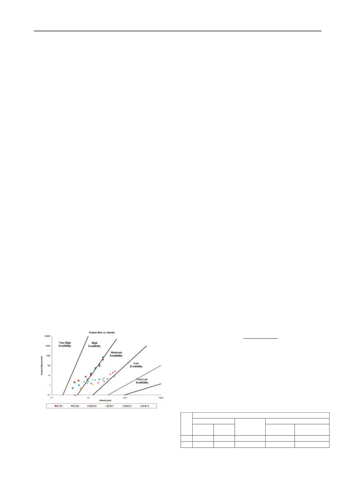
factors on the erosion resistance of a soil. Figure 1 presents the
EFA results for the two levees. From the investigation and
studies, it concluded that levee performance is influenced by the
flood conditions, the site conditions, and the soil properties.
Both sites in this study experienced large levels and durations of
overtopping water, but it is proposed that the Brevator site
survived because of its vegetative cover and more erosion
resistant soils. Erosion is a very complicated phenomenon that
cannot be described by any one parameter, but in all cases,
dense and consistent native vegetative cover can greatly
improve the overall levee performance.
Figure 1 EFA results for Winfield-Pin Oak – S1 and Brevator –
S3, Michelle B. (2011)
2.2 Internal erosion
Internal erosion caused by water seepage inside dike and
foundation is a major failure mode of river dike damage.
Actually, where there is a water head difference between
upstream side and downstream side, there is seepage in the dike.
With the rise of water level during flood period, the phreatic
line is formed inside the dike and its position gradually rises up.
At the same time, the seepage gradient in the dike and subsoil
gradually increased. When the actual seepage gradient (J) is
lager than the critical gradient of the subsoil (Jc), seepage
failure is occurred.
As all the seepage failures are driven by hydraulic gradient,
it could also be referred as hydraulic failure. The paper of H.
Brandl has discussed the hydraulic failure of river dike, which
include suffusion, contact erosion and internal erosion. The
measures to avoid hydraulic failure are also presented in the
paper. As internal erosion in dikes is not visible and difficult to
be detected before the failure happened, the method of early
diagnosis the possible internal erosion is significant in safety
assessment of dikes. The paper of J. Monnet summarized the
main methods for detecting dike internal erosion and presented
the application of a new in-situ test, the Cross Erosion Test
(CET), in Isère and Drac river levees in France.
Besides hydraulic conditions, the mechanism, procedure and
the result of seepage failure have very close relation with the
composition and properties of soil. Normally, dike seepage
failures can be classified into 4 types: mass flow (all particles
move by the force of flow), piping (fine grains flow though the
channels of coarse particles), contact mass flow (erosion along
the contact interface) and contact scouring. By analysis
characteristics of soil gradation, the mode of seepage failure of
each soil could be classified.
By large number of laboratory tests of different soils,
Chinese scholars have summarized systematic methods to
determine seepage mode of different soils.
According to the gradation, the non-cohesive soil can be
classified into two types: homogeneous (Cu
≤
5) and non-
homogeneous (Cu > 5). For non-homogeneous soil, it can
further be classified into two subtypes: discontinuous gradation
soil and continuous gradation soil.
For homogeneous soil (Cu
≤
5), there is only one failure
mode: mass flow. For the non-homogeneous soil (Cu > 5), the
failure mode depends on the gradation distribution. For soil
with discontinuous gradation, the failure mode is determined by
the content of fine grains (P). If P>35%, the failure mode is
mass flow. If P<25%, the failure mode is piping. If P=25
∼
35%,
the failure mode is intermediate type. For the soil with
continuous gradation, the failure mode is determined by content
of fine grains method.
For the content of fine grains method, the content of fine
grains at optimum gradation is introduced as an index. It is
defined as:
= 0.30 − + 3
1 −
n=porosity of the soil. If P>1.1P
op
, the failure mode is mass
flow. If P<0.9P
op
, the failure mode is piping. If P=(0.9
∼
1.1) P
op
,
the failure mode is intermediate.
The capability for resisting seepage failure is defined as the
limit seepage force (
γ
w
J) that a unit volume of soil can be
undertaken. The seepage gradient correspondent to this situation
is the failure hydraulic gradient (J
n
). Table 1 provides the
summarization of allowed gradient and failure gradient.
Table 1 The range seepage gradient
J
Seepage failure modes
Mass flow
Intermediate
Piping
C
u
≤
5
C
u
> 5
Continuous
gradation
Discontinuous
gradation
J
fe
0.8
∼
1.0 1.0
∼
1.5
0.4
∼
0.8
0.2
∼
0.4
0.1
∼
0.3
J
a
0.4
∼
0.5 0.5
∼
0.8
0.25
∼
0.4
0.15
∼
0.25
0.1
∼
0.2
For seepage safety of dikes, the primary goals of seepage
control in dikes and foundation could be summarized as three
aspects: (1) Decrease the quantities of seepage. (2) Release


