3277
Technical Committee 307 /
Comité technique 307
Proceedings of the 18
th
International Conference on Soil Mechanics and Geotechnical Engineering, Paris 2013
to be completely wrapped in the
geo
during the execution
of such operations is essential.
f
han
l
con
plan, is
r the top of
the
in at
either side to provide around half a bale width of overlap.
ler to the layer to vibrate the fill into the voids
(Fi
ve or
below the tyre bale layer must also be taken into account.
consolidated silts and clays, and soft predominately mineral
soils (albeit with exceptions). A geotextile helps to spread the
foundation load. Often the repair or reconstruction of an
existing road over soft ground is required as a result of
differential settlement which leaves an uneven surface with poor
ride quality and an increased risk of flooding. The placement of
material to raise and regulate the pavement surface increases the
formation load causing further differential settlement;
replacement of the existing material is thus necessary.
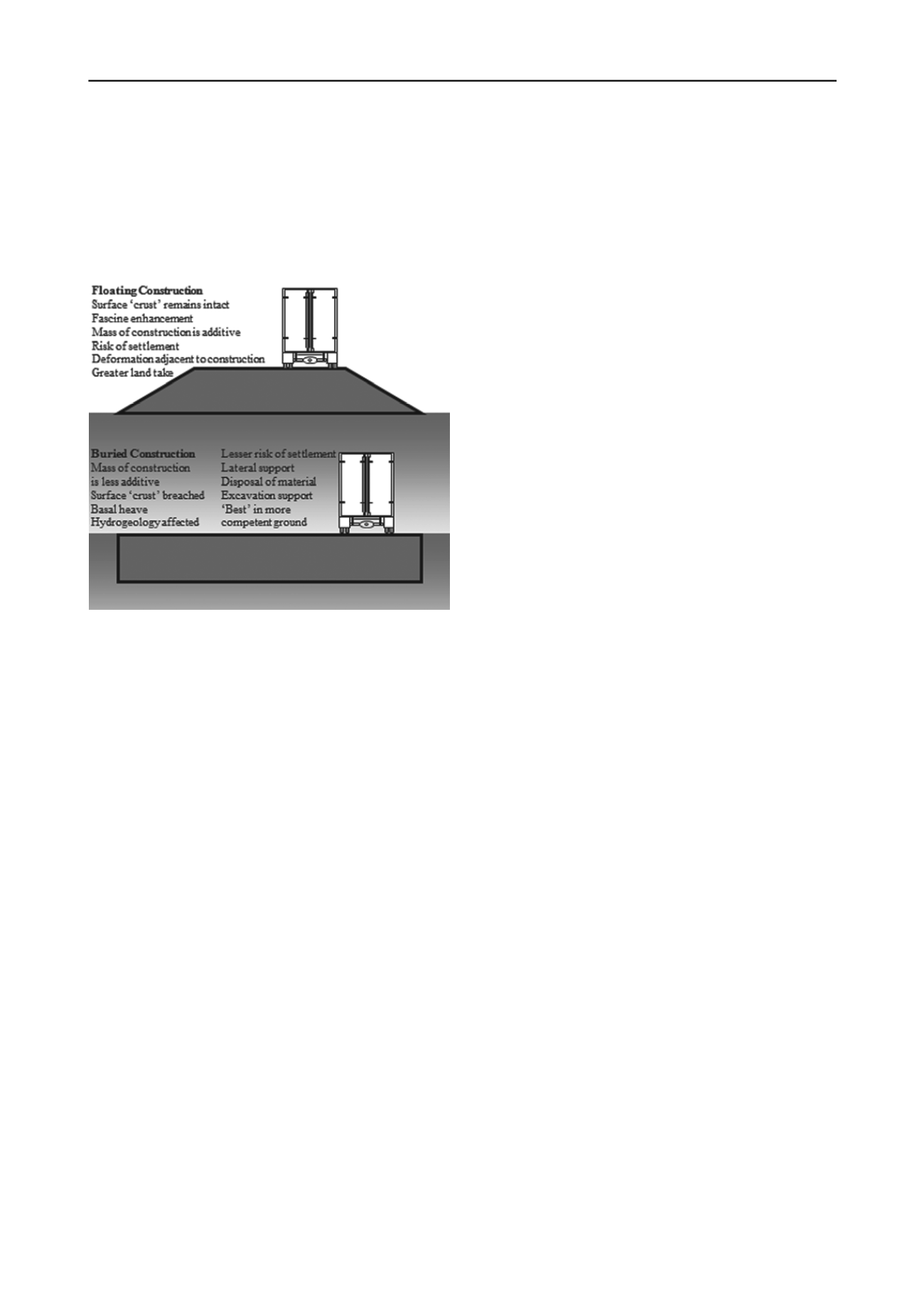
Figure 2. Advantages and disadvantages of floating construction (top)
and buried construction (bottom).
4 CONSTRUCTION APPROACHES
The construction and rehabilitation of low-volume roads over
soft ground is an ideal application for tyre bales. While there is
currently little information to prove their use with higher traffic
levels (in excess of a few hundred vehicles/day AADT) there
are no pressing reasons why such uses should not be successful.
Low-volume tyre bale roads have been successfully
constructed both above and below ground. A geotextile
separator is used between the in-situ soil and the tyre bales,
usually with a regulating layer of sand. The geotextile helps to
prevent differential movement of the bales during and after
construction. The decision as to whether the construction should
be above or below ground is an important determinant of the
approach to the design and construction.
Analytical input for low-volume road design on soft ground
is often limited. The strength and stiffness properties of the soil
involved are usually at or close to the lower limit of
measurement, rendering input parameters subject to large errors.
The sampling process may also disrupt the soil structure leading
to values lower than the field condition. Accordingly many
roads are designed on an empirical, specification-led basis.
The following sections summarises the main construction
steps and issues and offer guidance based upon experience of
successful projects and established good practice in constructing
low-volume roads over soft ground using tyre bales. Further
details are given by Winter et al. (2006) and Anon. (2007).
4.1
Excavation and preparation
For buried construction, excavation is the first construction
activity. Low ground-pressure, tracked plant is preferred as is
working in drier weather when the moisture content of the soil
is minimised and strength and stiffness are maximised.
A suitable geotextile should be installed either at ground
surface level or in the excavation followed by a regulating layer
of sand if required. All geotextile-to-geotextile interfaces should
have an overlap of 1m. The use of a geotextile has a number of
advantages including aiding working conditions in soft soils,
strengthening the structure by tying together the assembly of
bales, and providing separation between the bales and the
subsoil and thus preventing the ingress of fines. Randomly
orientated, bonded, non-woven geotextiles have been found to
be effective. Their main function is separation, with strength
and resistance to clogging the most important properties.
Geotextile design procedures should reflect local standards. The
geotextile should be placed in the base of the excavation, or on
the cleared ground. Sufficient excess should be allowed at either
side to allow the bale assembly
textile with a 1m overlap.
Rapid cellular construction minimises excavation size,
exposure of the soil to weather and the likelihood of side slope
failure. Bale sizes mean that excavations are unlikely to exceed
1m, but an assessment of the possibility of sidewall collapse and
the associated risks to workers and others
4.2
Placement and alignment
Tyre bale handling must incur the minimum risk of damage to
the steel tie-wires. The most successful means of handling tyre
bales has been found to be a ‘loggers’-clam’, which can be
attached to a variety of hydraulic equipment and provides an
appropriate lift-and-place methodology while allowing the bale
to be rotated to the correct alignment. Alternative forms o
dling bales include brick-grabs and forklifts (Anon. 2007).
The manufacturing process renders tyre bales inherently
heterogeneous. Information on the relative stiffness in each of
the three directions is not currently available. Tyre bales exhibit
a high stiffness when loads are applied vertically to the 1.3m by
1.55m plane (Figure 1); accordingly they are usually installed as
illustrated in Figure 1 for applications that attract high vertical
loads such as road foundations. The 1.55m by 0.8m plane is
perpendicular to the load applied during manufacture and it is
recommended that it is aligned perpendicular to the longitudina
fining stresses (i.e. with the tie-wires in line with the road.
While there are different layout options for the two-
dimensional placement of tyre bales (i.e. in a single layer) a
straightforward ‘chessboard’ pattern, as viewed in
generally the easiest to construct and is recommended.
A regulating layer of sand is normally required between the
top of the tyre bales and the geotextile wrapped ove
layer to help eliminate small variations in level.
The foregoing assumes that a single layer of bales is to
support the road. If two or more layers are required then the
second layer should be placed on top of the first, stepped
4.3
Filling of voids
The sub-rectangular shape of tyre bales means that voids remain
at the corners of each bale even when they are butted up against
one other. The design generally requires the stiffness and
stability of the structure to be maximized and thus the voids
should generally be filled (Figure 3). Coarse sand has been used
successfully as have single-sized aggregate pellets. Crushed
glass may be less likely to clog or arch than sand when wet, but
is expensive. The most effective method of ensuring that the
voids are filled has been found to be to bulldoze a 150mm to
300mm layer on top of the bale layer and then to apply a
vibrating rol
gure 3).
The fill material affects the density of the structure, with the
voids taking up an estimated 4% to 8% (Anon. 2007) of the
nominal rectangular bale volume, and must be allowed for in
design calculations. The effects of regulating layer(s) abo


