3286
Proceedings of the 18
th
International Conference on Soil Mechanics and Geotechnical Engineering, Paris 2013
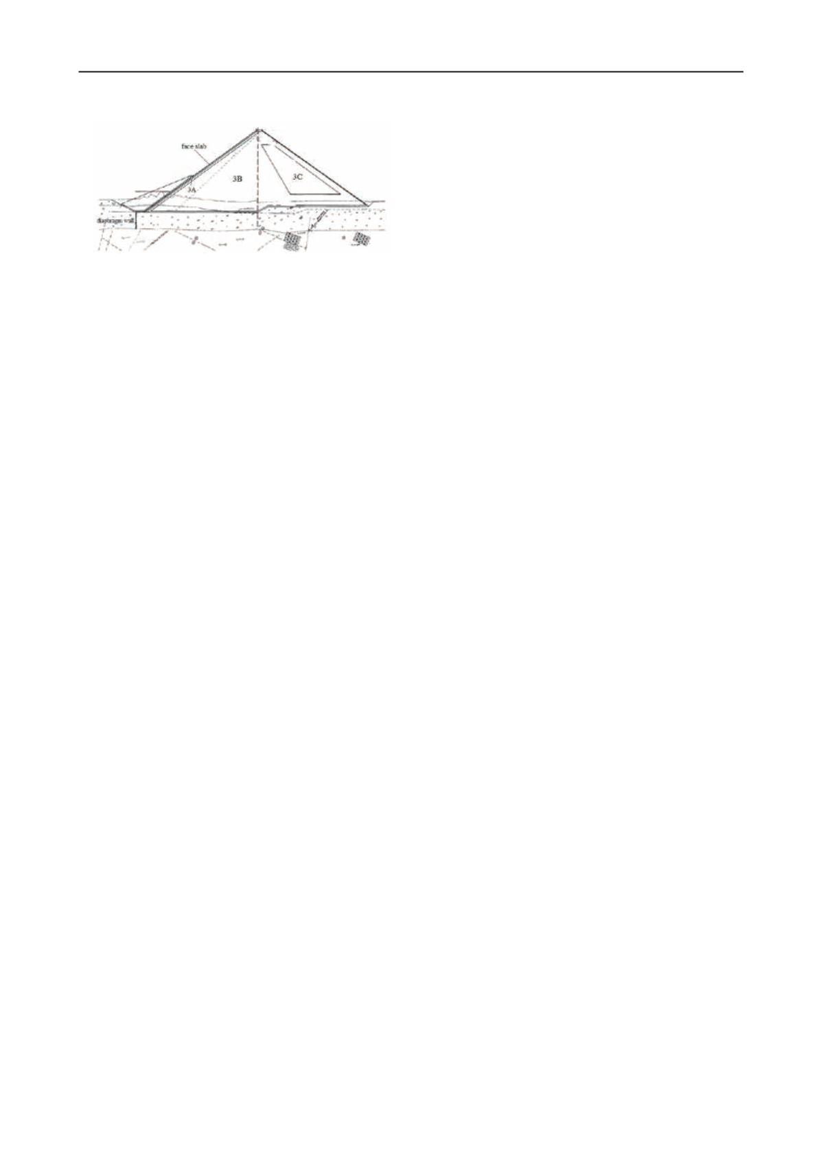
Figure 5 CFRD built on alluvium foundation
For high ECRD with the application of concrete diaphragm
wall for seepage control, one of the key issues is the connection
of diaphragm wall, earth core and gallery, and also the
connection of gallery with abutments. Generally, directly insert
diaphragm wall into earth core is more technically reliable.
When the top of diaphragm wall is connected to earth core by
gallery, differential displacement could be produced between
the wall and gallery. Joints should be arranged for the
connection. Also, the connection of gallery and abutments
should also arrange joints for adapting large differential
displacement.
For rock foundation, when bedrock exists geological defects
such as permeable stratum, fault fissures filled with erodible
materials, solution fissures or caverns, curtain grouting or
curtain grouting combined with consolidation grouting are
necessary. In design standard, the depth of grouting should
reach to impermeable layer. The permeability of rock stratum is
represented by Lugeon value (Lu). Usually, the value of 3
∼
5 Lu
could be applied for most of the rockfill dams foundation.
3.3 Control and coordination of dam deformation
In the design and construction of high rockfill dam, deformation
control is the most important issue. The stress statuses of
watertight barrier and dam operation performance are all related
with dam deformation. Therefore, the concept of integrated
deformation control and deformation coordination should be a
principle for the design and construction of high rockfill dam.
The main focus of this new concept includes two parts: (1) to
reduce the total quantities of dam deformation, (2) to coordinate
differential deformation between different zones.
Taking the example of CFRD, the ultimate purpose of
deformation control and deformation coordination will be the
safety of concrete face slabs and joint system. It could be
expressed as:
σ
< σ
σ
< σ
max(DP
)
max(DP
)
max(DP
) < D
D
D
Where:
σ
t
and
σ
c
are tensile and compressive strength of
concrete;
σ
s
and
σ
a
are stress of face slab in the direction of dam
slope and dam axis; DP
o
, DP
s
, DP
d
are displacements of joint
and D
o
, D
s
, D
d
are upper limit of joint displacement.
For high CFRD, the general principles of the integrated
deformation control and deformation coordination could be
summarized as follows:
The deformation of rockfill is directly related to lithologic
character, rockfill gradation, compaction density, dam height,
valley shape, etc.
In the design and construction of high CFRD, the low
compressibility and good gradation rockfill material should be
selected, and the compaction density should be strictly
controlled to reduce the overall deformation quantities of
rockfill.
In the design of high CFRD, material zones should be
arranged to achieve the coordination of deformations of
different parts of the dam.
In the construction of high CFRD, the construction stages of
rockfill and face slab should be well arranged to provide
sufficient time for deformation stabilization of upstream
rockfill.
The above principles could be expressed as:
S=F(H,H/A
2
,n,S
c
,C
s
)
n
≤
n
l
g
≤
s
p
, E
u
/E
d
≤
r
T
≥
t
p
Where: S is the maximum settlement of rockfill, H is dam
height, A is area of face slab; n is rockfill porosity (represent
compaction density); S
c
is uniaxial compressive strength of rock
(represent lithologic character); C
s
is coefficient of uniformity
(represent gradation of rockfill).
From the analysis of monitoring data and numerical analysis,
the control of rockfill deformation quantities could be
represented by the ratio of maximum settlement of rockfill to
the height of the dam. For CFRD with the height above 200m, d
is recommended to be controlled to 0.8%
∼
1.2%, that is:
S=dH (d=0.8%
∼
1.2%)
n
l
is the standard for rockfill porosity control. For CFRD
with the height above 200m, n
l
is recommended to be controlled
fewer than 20%. 18%
∼
20% is more favorable.
S
p
is the slope of the boundary between zone 3B and 3C. For
high dam, the boundary line should incline to downstream side.
The slope should not steeper than 1:0.5, i.e. S
p
≥
0.5.
r is the ratio of modulus of upstream and downstream
rockfill. For CFRD with the height above 200m, the modulus
ratio of upstream rockfill and downstream rockfill is
recommended be controlled below 1.5 to coordinate
deformation of upstream and downstream rockfill, i. e.
1.0
≤
r
≤
1.5.
t
p
is the time for upstream rockfill deformation completion.
To reduce the impact of rockfill deformation on stresses of
concrete face slab, certain period of time for rockfill
deformation should be provided before the construction of
concrete face slabs. Normally, the time is not less than three
months, i.e. t
p
≥
3 months. On the other hand, as the criteria for
assessing the completion of upstream rockfill deformation,
monthly settlement rate of less than 3
∼
5mm is the
recommended as control values.
In addition to the control of deformation quantities, the new
concept more emphasizes on the coordination of deformations
between different dam zones. For high CFRD, it includes the
deformation coordination for the rockfill of upstream and
downstream, abutment area and riverbed area, upper part and
lower part, and also, the deformation coordination of concrete
face slab and upstream rockfill, and rockfill constructed in
different stages. For high ECRD, the focus is on the
coordination of deformation of rockfill shell and earth core to
avoid harmful cracks on earth core.
In the paper submitted by N. Li, the methods for assessing
deformation coordination of CFRD were proposed, which
include settlement, horizontal displacement and deflection of
concrete face slab (Li 2013). The propose concept was applied
in the design and construction of Bakun CFRD. In the paper
submitted by Y. Chen, three-dimensional numerical analysis of
a high CFRD was presented. From the results of analysis, it is
noticed that the large deformation of rockfill and differential
displacement between rockfill and face slabs will cause the
cracks on concrete face slabs (Chen 2013).


