3292
Proceedings of the 18
th
International Conference on Soil Mechanics and Geotechnical Engineering, Paris 2013
4 DESIGN CRITERIA FOR RELIEF DRAINAGES
AND ASSESSMENT OF WATTERLOGGING
Until now the design of relief measures (drainage columns or
trenches) is based on rather insufficient basic principles, strong
simplifications and idealizations. For the quantification of the
water outflow from relief columns as well as for a pressure
assessment beneath the cover layer only assumptions based on
numerical models are in use. These approaches allow indeed
comparative calculations of the quantity of seepage through and
under the dyke (Fig. 6). But they do not allow an exact
differentiation of the waterlogging from flood, precipitation and
groundwater of the hinterland. Accordingly, the design of
polders and pumping stations can be performed only based on
estimated water outflows from the relief drainages.
Figure 6. Simplified numerical model of a dyke with relief columns.
Nowadays the assessment of waterlogging is carried
out mainly by mapping of water logged areas along the river
after floods or heavy rainfalls in combination with digital
elevation models (Fig. 7). The results are then combined with
numerical simulation studies. Such a long-term monitoring
gives some information about the outflow from the relief
drainages as well as about the water distribution in the
hinterland of the dyke. But it does not allow a detailed design of
specific technical measures.
Figure 7. Mapping results for waterlogging with different origin.
Consequently, 1:1 scale model tests on dykes
including the subgrade are the best solution to quantify the
water outflow from the relief elements during flood stages.
Experimental tests performed under laboratory conditions allow
a higher degree of reliability than mere numerical simulations.
Based on the results from physical modelling an exact
calibration of numerical models can be performed.
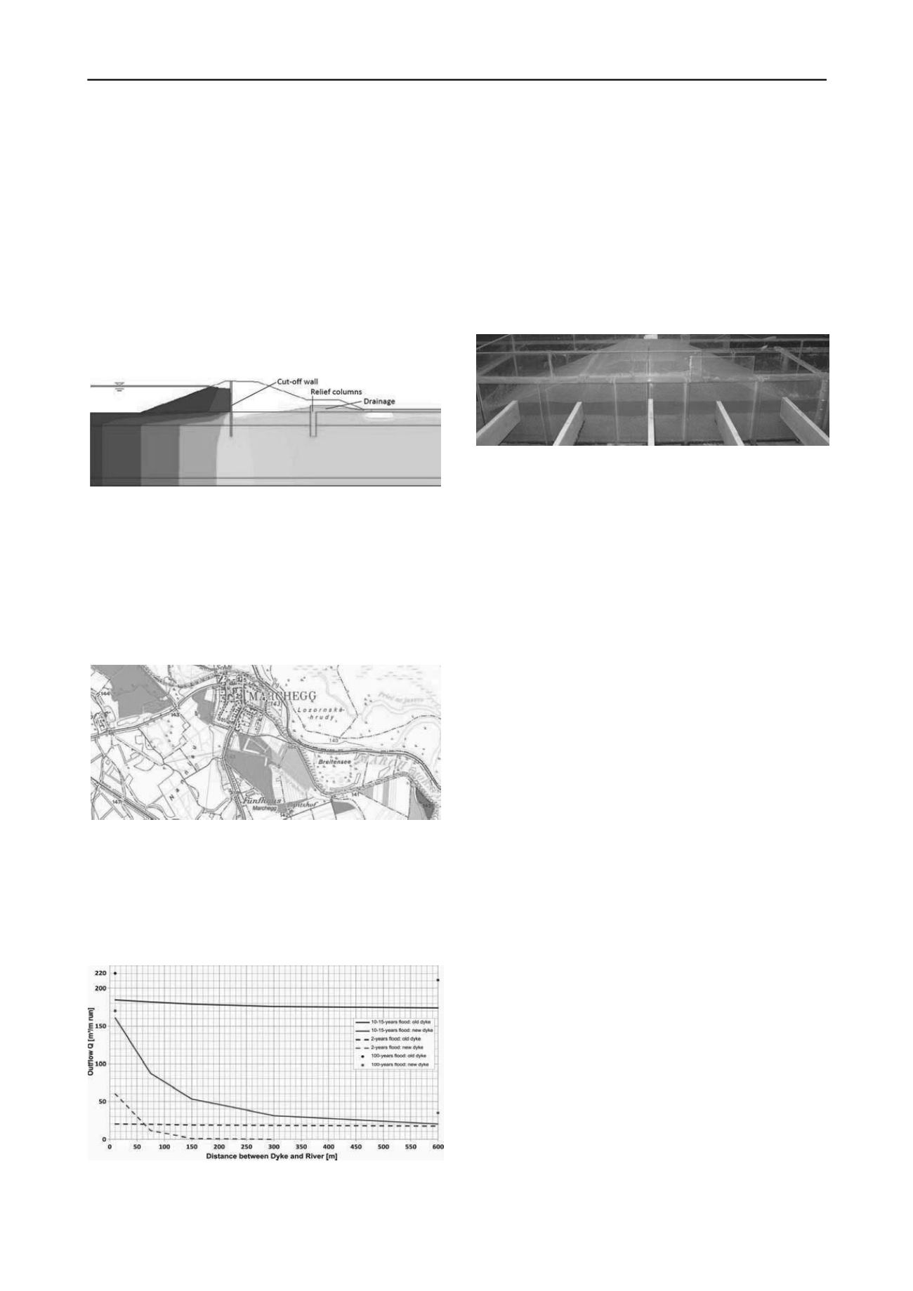
Figure 8. Water outflow Q from the relief drainage versus the distance
between riverbed and old or new dyke resp. for different flood events.
In generally, the applicability of results from mere
numerical modelling onto natural flow behaviour is strongly
limited because of many parameters and boundary conditions.
The quantity of water outflow through the relief columns is
mainly influenced by subgrade/soil properties, flood wave
characteristics, volume of unsaturated aquifer, distance between
dyke and riverbed etc. Figure 8 shows the relation between the
outflow and distance criterion for an old dyke (insufficient
drainage) and the new one (with relief columns).
In the first phase of experimental underseepage
studies small-scale (1:10) model tests were carried out at the
Vienna University of Technology, Institute of Geotechnics
(Fig. 9). The tests results were used for the design of an
experimental station for 1:1 scale model tests.
Figure 9. Small-scale model test of a flood protection dyke with
simulated subgrade (fine-grained cover layer and permeable aquifer).
5 CONCLUSIONS
In the long-term underspeepage of dykes may lead to
erosion processes of the fine-grained soil layers during floods.
The hydraulic failure develops mostly very inconspicuously;
therefore it is often underestimated in practice. Erosion criteria
can be used to describe the critical state for different soil types
found during soil investigation. For hydraulic failure prevention
landside the dyke filter stable berms or relief columns or
trenches have proven.
A technically and economically optimized design of
relief measures can be achieved only by combining physical and
numerical models. Such a combination takes the specific
advantages of both methods. Based on physical model tests a
calibration of the numerical model allows detailed parametric
studies and makes an application of these results as design
criteria generally possible.
6 REFERENCES
Darcy H. 1856.
Les fontaines publiques de la ville de Dijon
. Dalmont,
Paris.
Brandl, H. & Hofmann, R. (2006). Erosionsstabilität und Stand-
sicherheit von Schutzdämmen gegen Wildbäche und Murengänge
mit besonderer Berücksichtigung von Einbauten. Sicherung von
Dämmen, Deichen und Stauanlagen, Hermann, R. A., Jensen, J.,
Editors, Univ. Siegen, Germany, vol. I., pp. 139 – 171.
CEN (2004). EN 1997-1: Eurocode 7: Geotechnical Design – Part 1:
General Rules. Comiteé Europeén de Normalisation, Brussels.
Chugaev, R. R. (1965). Calculation of the filter stability of the ground
below dams. Gidrotechniceskoe Stroitel’stvo, No. 2 (in Russian).
Giroud, J. P. (2010). Development of criteria for geotextiles and
granular filters. Prestigious Lecture 1. Proceedings of the 9
th
International Conf. on Geosynthetics, Guaruja´, Brazil, pp. 45 – 66.
Heibaum, M., Fourie, A., Girard, H., Karunararne, G. G., Lafleur, J. &
McGrath, J. (2006). Hydraulic application of geosynthetics. Special
Lecture. Proceedings of the International Conference on
Geosynthetics (IGS), Yokohama, Japan, Millpress, Rotterdam, the
Nether- lands, pp. 79 – 120.
Nagy, L. (2011). Investigation of soils outwashed from piping.
Österreichische Ingenieur- und Architekten-Zeitschrift, Jhg. 156,
No. 1-12/2011, p. 211-215.
Ziems,
J.
(1967).
Neue
Erkenntnisse
hinsichtlich
der
Verformungsbeständigkeit
der
Lockergesteine
gegenüber
Wirkungen des Sickerwassers. Wasserwirtschaft – Wassertechnik
17, No. 7, 50 – 55 (in German).


