3306
Proceedings of the 18
th
International Conference on Soil Mechanics and Geotechnical Engineering, Paris 2013
1.2
Classical methods for analyzing rapid drawdown
Drawdown condition has been analyzed from different
approaches depending on the progress in the field of classical
soil mechanics. The analysis methods can be classified into two
groups (Alonso and Pinyol 2008): a) water flow methods
appropriated for and relatively permeable materials, b)
undrained analysis methods applicable to low permeability
materials.
The methods included in the first group solve the water flow
problem within an earth slope subjected to changes of hydraulic
boundary conditions as a function of time. According to these
methods it is implicitly accepted that the solid skeleton of the
materials involved in the drawdown phenomenon is rigid and no
changes occur in the total stresses. Usually, recommendations
for the study of relatively permeable materials are based on
numerical, analytical or graphical groundwater flow techniques.
However, these types of water flow methods do not consider the
soil deformability which in the case of soft materials plays an
important role in the velocity of dissipation of the pore water
pressure.
The second approach considers only the pore water pressure
change due to discharge of stresses associated to decrease of
water level during the water drawdown phenomenon
(mechanical problem). That is, the analysis is undrained type, in
which water flow is negligible because of the significant
drawdown rate compared with the permeability of material.
2 PROPOSED METHODOLOGY FOR ANALYSES
The stability analysis of a protection levee under rapid
drawdown conditions requires the consideration of two effects:
i) changes in total stresses due to external loads, such as
hydrostatic pressure or overloading (e. g. bank protections
sandbags, over-elevation on a levee height, etc.), and ii) seepage
forces due to transient groundwater flow. According to the
Terzaghi’s principle (1943), the increase in total stresses in a
saturated soil is equal to the sum of the effective stress plus the
pore water pressure:
=
+
p
=
+ (
p
seepage
+
p
excess
)
(1)
Where
is the change in total stresses,
is the change in
effective stresses and
p
is the change in active pore water
pressure, which is constituted by pore water pressure increases
due to seepage (
p
seepage
) and pore water pressure increases due
to changes in total stresses.
The pore water pressure due to seepage is computed by a
water flow analysis. If the flow domain contains a water table
that changes as a function of time, the problem becomes one of
transient flow type. The excess pore water pressure due to
changes in the total stresses is calculated by a stress-strain
analysis. This pressure is not steady-state and changes with time
(it increases or dissipates); therefore it also is a problem that
requires be evaluated versus time. Additionally, during
drawdown the dissipation of remaining pore water pressure
(consolidation) may occur depending on material properties,
drawdown rate and drawdown ratio. Consequently, to evaluate
the stability of an earth structure subjected to rapid drawdown
condition, it is required the coupling of the following analyses:
i) Transient-state seepage analysis.
ii) Deformation analysis.
iii) Consolidation analysis.
iv) Stability analysis.
Currently, numerical techniques are the most common
solution, specially the finite element method. The preceding
methodology is applied in the analyses performed herein, with a
2D plane-strain model using finite element programs:
PLAXFLOW for the transient seepage analyses and PLAXIS
for the deformation, consolidation and stability analyses (Delft
University of Technology 2008), as shown below.
3 PARAMETRIC ANALYSES
3.1
Problem statement
In order to investigate the influence of rapid drawdown on
stability of protection levees, analyses assuming the three
different drawdown modes illustrated in Figure 1 were
performed. For the
fully slow drawdown
mode, soil was
assumed to be drained and only water flow analyses were
carried out (uncoupled). For the
fully rapid drawdown
mode,
soil was considered undrained and only undrained analyses
were performed (uncoupled). For
transient drawdown
(Fig. 1b),
a coupled analysis was performed and soil was assumed to be
undrained.
3.2
Geometric, hydraulic and mechanical properties, and
initial and boundary conditions
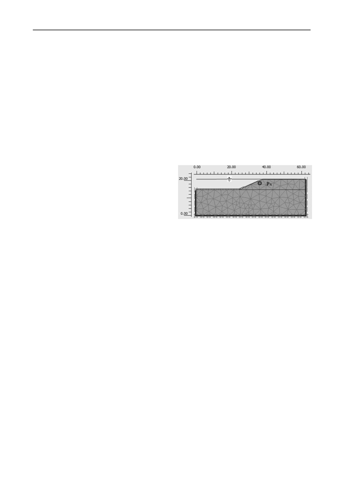
A homogeneous and isotropic levee (H = 6 m height and 2:1
slope) was considered in analyses, as illustrated in Figure 2.
Figure 2. Simplified geometry of the analyzed levee.
The mechanical, hydraulic and rigidity properties of both the
levee and the foundation soil were assumed in calculations as
provided in Table 1. Similarly, in the analyses two different
hydraulic conductivities (
k
=1×10
-4
and 1×10
-6
cm/s) and two
drawdown rates (
R=
0.1 m/d and 1.0 m/d) were studied. The
capacity of soil to retain water was defined by the
approximate
Van Genuchten model
(1980).
For modeling the domain a fairly refined mesh was
generated by using 15 nodes triangular finite elements, because
they provide more accurate results in more complex problems,
such as bearing capacity and stability analyses (Nagtegaal
et al
.
1974, Sloan 1981, Sloan and Randolph 1982). Standard
boundary conditions were assumed (fixed bottom). The initial
stress state was generated by using the K0 procedure. All model
boundaries were considered to be impervious, except the
surface of foundation soil, the slope and crown of the levee (see
Fig. 2). It was also assumed that the reservoir level is initially
located at the maximum elevation (21 m, corresponding to
L=0).
3.3
Numerical modeling
For the numerical modeling of the problem, it was initially
assumed that flow conditions within the embankment
correspond to a steady-state (
t
= 0;
L
/
H
= 0), thus a steady-
state flow analysis was firstly performed, which was followed
by deformation and consolidation analyses. In this last analysis,
a minimum pore water pressure was assumed within the levee
(
p
excess
= 0.1 kPa), because the study is performed supposing
that elapsed time is long enough to allow that the excess pore
water pressure caused by the filling of the reservoir is
dissipated. The relation
L
/
H
is called
drawdown ratio
, where
L
represents the position of the water level in the reservoir with
respect to the crown of the levee at the end of each stage of the
drawdown, and
H
is the height of the levee.
Subsequently, the drawdown phenomenon was simulated
considering 5 stages (L/H = 0.2, 0.4, 0.6, 0.8 and 1), starting
from level L = 1.2 m up to level L = 6 m (the total drawdown in
this study). Each stage represents a time of the drawdown (
t =


