 
          3144
        
        
          Proceedings of the 18
        
        
          th
        
        
          International Conference on Soil Mechanics and Geotechnical Engineering, Paris 2013
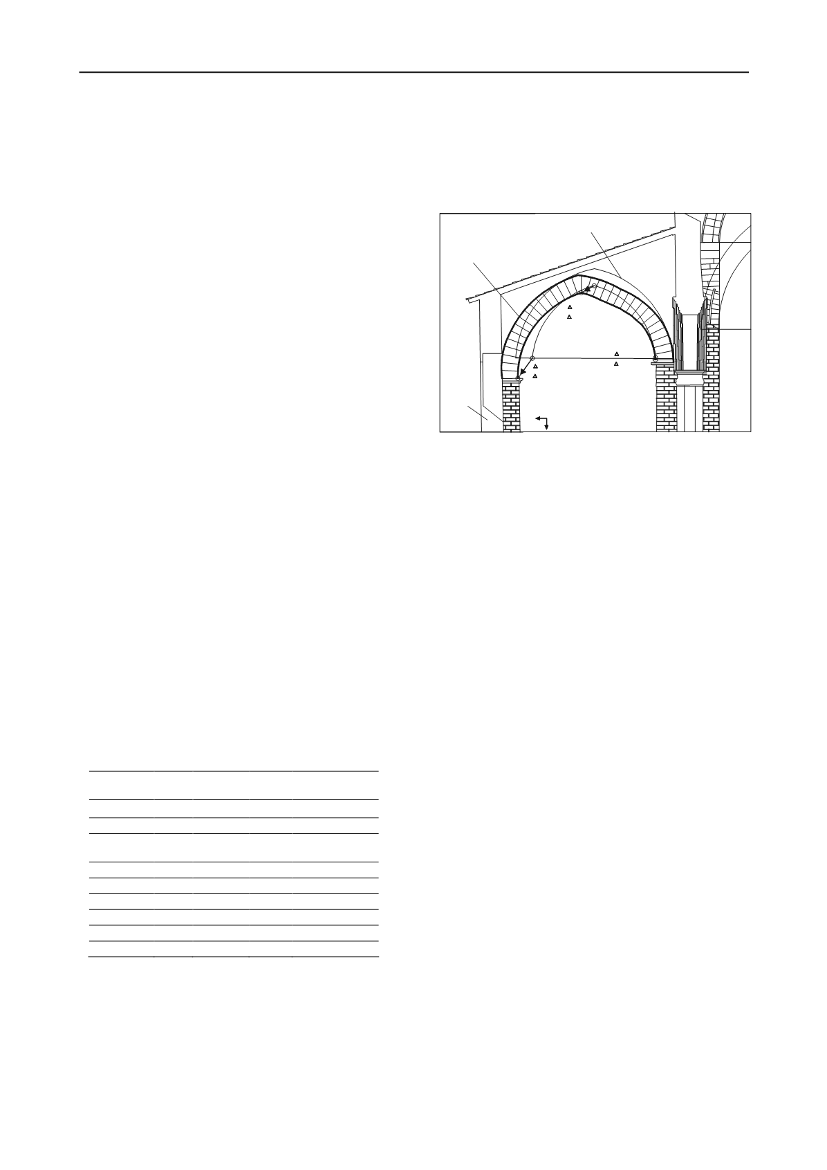
        
        
          Present shape
        
        
          Likely original shape
        
        
          Northern
        
        
          wall
        
        
          y
        
        
          x
        
        
          x=0.01m
        
        
          y=0.09m
        
        
          x=0.69m
        
        
          y=0.93m
        
        
          x=0.58m
        
        
          y=0.30m
        
        
          An idea of the cumulative differential settlements and
        
        
          horizontal displacements towards the slope of the northern
        
        
          wall can be drawn from the deformed shape of an arch
        
        
          transversal to the axis of the northern aisle and adjacent to the
        
        
          transept. According to a fairly credible reconstruction depicted
        
        
          in Fig. 3, the northern springline of the arch might have
        
        
          undergone an horizontal displacement so large as 69 cm and a
        
        
          settlement of 93 cm relative to the other springline.
        
        
          The pattern of the present-day fissuration and movements
        
        
          remarkably resembles that observed recurrently since 1904 as
        
        
          documented by photos and descriptions recorded in archival
        
        
          sources (Di Fede, 2011).
        
        
          The relevant inclinometer readings, begun on June 2011
        
        
          and summarized in Tab. 3, show that the ground mass located
        
        
          downhill of the longitudinal fracture undergoes significant
        
        
          horizontal displacements and point out the existence of shear
        
        
          surfaces at depths between 7 and 17m.
        
        
          Based on these data and observations it is possible to
        
        
          identify a slide mechanism shown in Fig. 2. Similar
        
        
          mechanisms apply for the whole length of the Cathedral and
        
        
          the parvis zone, the archiepiscopal palace and Ismani
        
        
          hypogeum.
        
        
          The above mechanism appear to be the main reason for the
        
        
          anomalous behaviour of the ground-Cathedral system. It has
        
        
          not been identified nor postulated up to now, and
        
        
          consequently the attempts to stabilise the Cathedral were
        
        
          unfounded. The sliding mechanism passes along the
        
        
          subvertical fracture and through silty sands SL and altered
        
        
          clays AGG. A stability analysis of this sliding mechanism,
        
        
          which involves the North aisle of the Cathedral, points out
        
        
          that the use of peak or residual shear strength parameters of
        
        
          soils SL and AGG is not warranted. In fact, if peak
        
        
          parameters are considered values of the factor of safety FS
        
        
          within the range 1.4-1.6 will be calculated, whether if residual
        
        
          strength is considered a value of FS much smaller that 1 is
        
        
          obtained: these values are inconsistent with the observed
        
        
          behaviour of the ground-Cathedral system. It is likely that the
        
        
          shear strength is gradually approaching the fully softened
        
        
          value for which the value of FS is 1.05.
        
        
          Table 3. Superficial (top) horizontal displacement


            h


          , and depth


            d


          of
        
        
          sliding surface indicated by inclinometric measurements from June
        
        
          2011 to Dec. 2012. Location of inclinometer tubes relative to the
        
        
          longitudinal fracture. U: uphill; D:downhill. N: north; NW: north-
        
        
          west.
        
        
          Inclinometer
        
        
          tube


            h


            (mm) Direction


            d


          (m)


            Location


          S1*
        
        
          2
        
        
          /
        
        
          /
        
        
          U
        
        
          S2*
        
        
          12.8
        
        
          NW 7
        
        
          D
        
        
          S3*
        
        
          6
        
        
          N 15;
        
        
          22
        
        
          D
        
        
          S4*
        
        
          4
        
        
          /
        
        
          /
        
        
          U
        
        
          S13
        
        
          3.2
        
        
          /
        
        
          /
        
        
          U
        
        
          S16
        
        
          8
        
        
          NW 11;16
        
        
          D
        
        
          S20
        
        
          8.3
        
        
          N 17
        
        
          D
        
        
          S22
        
        
          10
        
        
          NW 6; 11
        
        
          D
        
        
          S26
        
        
          2.3
        
        
          /
        
        
          /
        
        
          U
        
        
          8 CONCLUSIONS
        
        
          The behaviour of Agrigento Cathedral has been
        
        
          unsatisfactory since its construction in the XI century on the
        
        
          crest of a very steep slope. Many attempts to stabilise the
        
        
          ground-Cathedral system have failed because a sound
        
        
          diagnosis of its problems has not been formulated.
        
        
          Recent geotechnical investigations permitted to identify a
        
        
          rather large sliding mechanism involving the North aisle of
        
        
          the Cathedral as well as long adjacent stretches of the edge of
        
        
          the slope. It is now evident that the preservation of the
        
        
          Cathedral requires prioritarily the stabilisation of the slope.
        
        
          Fig. 3. Distorted arch located at the eastern extremity of the North
        
        
          aisle showing large differential movements between the springlines
        
        
          cumulated probably during some centuries. (Reconstruction by Arch.
        
        
          G. Renda).
        
        
          9 REFERENCES
        
        
          Commissione del Ministero dei Lavori Pubblici della Repubblica
        
        
          Italiana, 1968.


            Technical Report on the 1966 Agrigento


            Landslide.


          Città Spazio, N° 1-2. (In Italian).
        
        
          Cotecchia V., Fiorillo F., Monterisi L., Pagliarulo R., 2005. Slope
        
        
          instability in the Valley of Temples, Agrigento (Sicily).


            Giornale di Geologia Applicata


          , 91, 91-101.
        
        
          Croce A., De Miro E., Fenelli G.B., Jappelli R., Liguori V., Morandi
        
        
          R., Nocilla N., Pace E., Pellegrino A., Rossi Doria P., 1980.
        
        
          Agrigento town and the Valley of Temples. Problems of
        
        
          stability of the territory and of preservation of monuments.


            Atti


            del XIV Conv. Naz. di Geotecnica


          , Florence, 1, 109-124. (In
        
        
          Italian).
        
        
          Di Fede M.S., 2010. L’ “invenzione”
        
        
          della Cattedrale interventi di
        
        
          restauro nella prima metà del Novecento. In G. Ingaglio
        
        
          (editor):


            La Cattedrale di Agrigento tra storia, arte,


            architettura


          . Edizioni Caracol, Palermo, 167-186. (In Italian).
        
        
          Lizzi F., 1993. ‘Pali radice’ structures.
        
        
          In S. Thorburn and G.S.
        
        
          Litteljohn (editors),


            Underpinning and retention


          . Blackie
        
        
          Academic & Professional, London, 84-156.
        
        
          SYMBOLS


            c


            p


          peak cohesion intercept


            E


          Young modulus


            E


            ed


          constrained modulus


            CF


          clay fraction


            k


          coefficient of permeability


            n


          porosity


            S


          saturation degree


            w


          l
        
        
          liquid limit


            w


          p
        
        
          plasticity limit


            w


          n
        
        
          natural water content


            p


          peak angle of shear strength


            r


          angle of residual shear strength


            s


          specific weight


            sat


          saturated unit weight


            f


          uniaxial strength