 
          3143
        
        
          Technical Committee 301 /


            Comité technique 301


          CL,whilst the northern wall and a small stretch of western
        
        
          (facade) wall rest on intensely fractured calcarenites or on
        
        
          silty sands SL, see Fig. 2. The columns have been
        
        
          underpinned by groups of fourteen “root piles” about 15 m
        
        
          long, slightly inclined to the vertical so to describe a ruled
        
        
          surface flaring downwards (Lizzi, 1993). Each root pile was
        
        
          reinforced with a single, 24 mm diameter, steel bar. Shorter
        
        
          root piles were used to underpin the northern wall of the
        
        
          Cathedral. Root piles groups under the nave columns have
        
        
          been tied at the top by a grid of reinforced concrete beams. It
        
        
          is clear from Fig. 2 that the foundation ground of the
        
        
          Cathedral is far from uniform and that the thickness of the soft
        
        
          calcarenite layer CL diminishes or vanishes as the northern
        
        
          slope is approached. During the underpinning works in 1976-
        
        
          1980 it was ascertained that the CL calcarenite layer was
        
        
          dissected by a long and deep fracture (or tension crack)
        
        
          located inside the Cathedral near the northern wall, as shown
        
        
          in figures 1 and 2; it was “stitched” by cement pressure
        
        
          grouting.
        
        
          7 GROUND MOVEMENTS, FISSURATION PATTERN
        
        
          OF THE CATHEDRAL AND CAUSES OF ITS
        
        
          UNSATISFACTORY BEHAVIOUR
        
        
          The most striking sign of ground movement is a
        
        
          longitudinal subvertical tension crack running in East-West
        
        
          direction through the floor of the northern aisle, and extending
        
        
          continuously to the parvis, the staircase and the Don Minzoni
        
        
          square, and in the opposite direction to the apse, the
        
        
          archiepiscopal palace and the Ismani Hypogeum as shown in
        
        
          Fig.1. This fracture has been firstly surveyed by Commissione
        
        
          del Ministero dei Lavori Pubblici for the investigation of the
        
        
          great
        
        
          “
        
        
          Addolorata landslide
        
        
          ”
        
        
          (1968). The aperture of this
        
        
          fracture exceeds more than 20 centimeters in the Ismani
        
        
          hypogeum. After the restoration works completed in 2000, the
        
        
          fracture formed again in the Cathedral floor and in the parvis;
        
        
          its aperture slowly progresses and has now attained 4 cm.
        
        
          There is a step, from 2 to 3 cm high, between the northern and
        
        
          the southern walls of the fracture. The northern wall settled
        
        
          about 4 cm
        
        
          The floor of the nave and the southern aisle have
        
        
          undergone negligible settlements.
        
        
          Table 1. Geotechnical properties of soils R, SL, AG, AGG.
        
        
          Soil


            w


            n


          (%)


            w


            l


          (%)


            w


            p


          (%)


            S


          (%)


            CF


          (%)


            s


          (kN/m
        
        
          3
        
        
          )


            sat


          (kN/m
        
        
          3
        
        
          )


            c


            p


          (kPa)


            p


          (°)


            r


          (°)


            E


            ed


          (MPa)
        
        
          R
        
        
          /
        
        
          /
        
        
          /
        
        
          /
        
        
          /
        
        
          /
        
        
          /
        
        
          0
        
        
          30-35
        
        
          /
        
        
          /
        
        
          SL 11-28
        
        
          35-40
        
        
          18-23 100
        
        
          2-10
        
        
          27-27.4 19.5-20.5 15-25 29-30
        
        
          /
        
        
          4-20
        
        
          AGG 18-30
        
        
          45-55
        
        
          20-22 100 35-45
        
        
          26.8-27.3 19.6-20.5 30-35 27-29
        
        
          14 10-40
        
        
          AG 18-30
        
        
          43-51 20-23.3 100 31-43
        
        
          26.9-27.4 20.2-20.7 30-40 28-30
        
        
          16 20-60
        
        
          Table 2. Geotechnical properties of calcarenites CL and CLR.
        
        
          Calcarenite


            n


          (%)


            s


          (kN/m
        
        
          3
        
        
          )


            sat


          (kN/m
        
        
          3
        
        
          )


            f


          (MPa)


            k


          (cm/s)


            E


          (MPa)
        
        
          CL and CLR 0.36-0.46 26.9-27.4 18.8-20.6
        
        
          1.1-4.6
        
        
          10
        
        
          -2
        
        
          - 10
        
        
          -4
        
        
          300-700
        
        
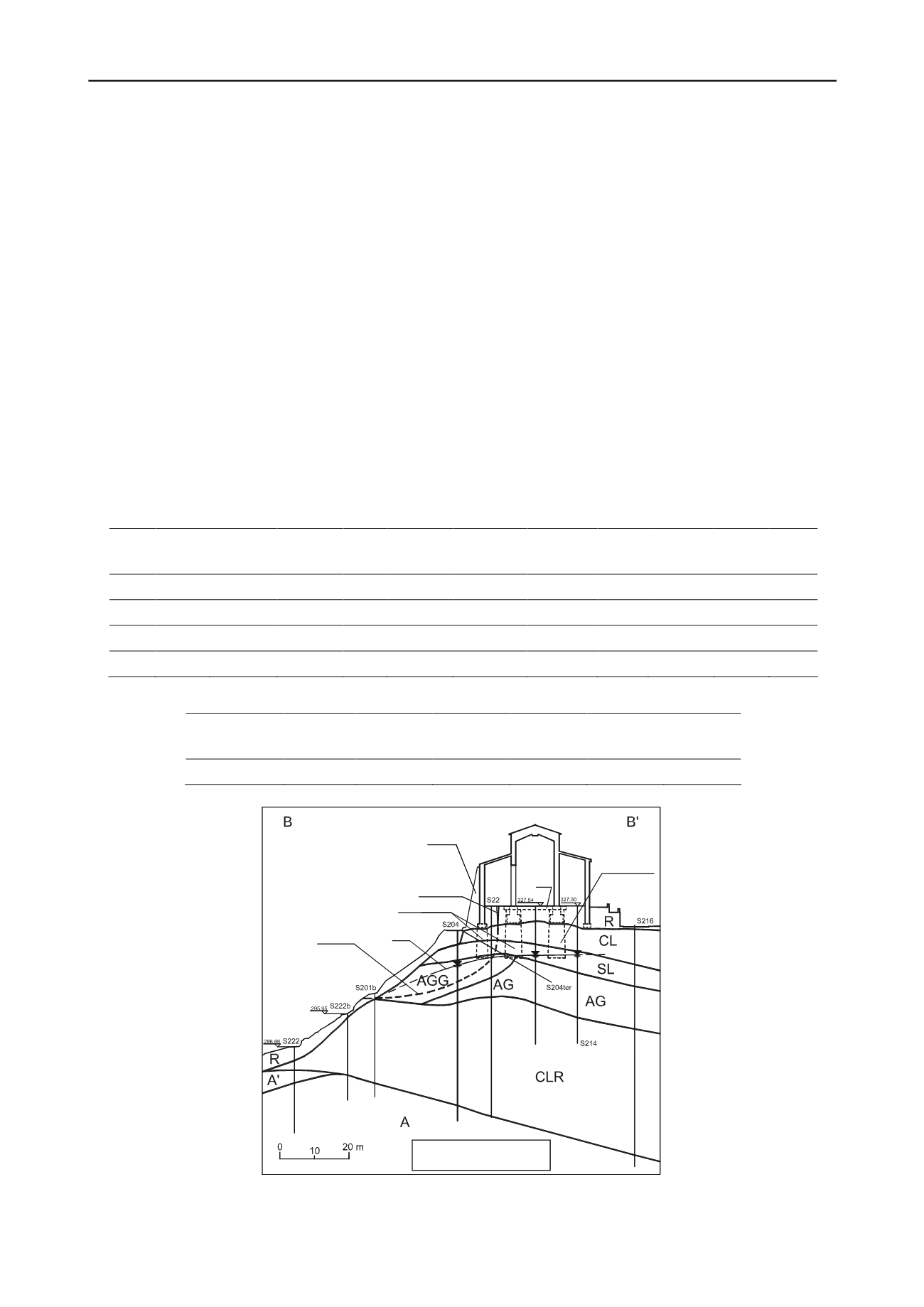
          Fig. 2. Vertical cross ground profile B-B


          . R: made ground or topsoil; CL: upper soft yellowish or reddish biocalcarenites interbedded with sand
        
        
          lenses; SL: silty sands and sandy silts; AG: grey clays; AGG: grey-yellowish or light brown clay with veins of minute crystals of secondary gypsum;
        
        
          CLR: lower soft reddish biocalcarenites with sand lenses; A: heavily overconsolidated grey clays; A


          : grey-yellowish clays with gypsum veins.
        
        
          S211
        
        
          Tension crack
        
        
          Duomo
        
        
          street
        
        
          Slip surface
        
        
          Root piles group
        
        
          Root piles group
        
        
          RCB
        
        
          RCB Reinforced concrete beam
        
        
          (*) Elevation m a.m.s.l.
        
        
          GWT
        
        
          Buttress
        
        
          (*)