3151
Technical Committee 301 /
Comité technique 301
settlement of the tested pile is depending on category of
construction and is equal 16 or 24 mm. The last argument
shows conditional character of SLT method.
According to Kazakhstan Standard 1% of constructed piles
on construction site must be tested by SLT, but at least 2 SLTs
in a site must be done.
Comparison of SLT and DLT
.
SLT and DLT both are
practiced in Kazakhstan construction. According to experience
on construction sites of Astana, some difference exists between
SLT and DLT results. Moreover, results of bearing capacity of
pile depend on type of hammer. Thus, DLT results obtained by
using hydro-hammer are more approximate to the SLT results,
namely more reliable than results obtained by using diesel
hammer (Ashkey Y. 2008). The safety factor as defined by
comparative analysis of many DLT and SLT data is presented in
Figure 4.
Figure 4. Comparison SLT and DLT
Alternative Load Test Method
. From aforementioned it
follows that SLT and DLT both have disadvantages. SLT
required a lot of time, works and cost. Prescribed by Standard
quantity of required SLT is not enough to adequately realize soil
condition of construction site (2 SLT for 200 piles only). DLT
is much faster but is not so reliable and is applicable to driving
piles only.
Alternative load test method which precluded disadvantages
of both SLT and DLT was used on this construction site – Pile
Dynamic Analysis Method (PDA). PDA allows tests up to 10
piles per day and much cost effective than SLT. The
comparison of SLT, DLT and PDA approved superiority of Pile
Dynamic Analysis Method.
The O-cell bi-directional test of bored piles was firstly used
on construction site of Astana. The general advantages of this
method as compared with SLT and DLT are follows: no anchor
piles, no external reaction system, no heavy transport is
required, only half the stresses applied to the concrete,
significant cost saving as loads increase.
Quality control of pile foundation.
Pile integrity test is one of
the non-destructive methods of pile quality control. This method
allows analyzing integrity control for all existing types of piles
(boring, injection, driving and so on). PIT is base on wave
propagation theory in rigid body and is concerned with one of
the modern quality control methods used world-wide. PIT
allows detecting pile defects: approximate pile length,
expansion and narrowing of pile cross section, modification of
soil layers, heterogeneity of pile material, cracks in cross
section of pile, extrinsic material in pile body.
Advantages of PIT are as follows: portable device is easy to
carry. One operator will be able to test over 100 piles per day,
depends on site condition, pile head preparation and approach to
the pile; minimum influence to the construction work on the
site; significant defects may be detected in the beginning of the
construction. PIT has some limitations: reflection of the bottom
of pile sometimes has errors depending on soil condition; little
deflection (less than 5 %) of pile cross section cannot be
identified.
According to Kazakhstan Standard requirements it is
necessary to test 60% of boring piles and 50% of driving piles.
Geomonitoring.
Geomonitoring for foundation settlement is
one of the quality control methods that can be carried out during
and after construction in exploitation period. Monitoring is
indirect control of pile installation evaluation.
The principle of this method is monitoring the settlement of
special marks which are installed to interested points of
construction. Monitoring starts from the beginning of
construction and allows revealing defects of foundation
installation.
4 COMPARISON OF SLT RESULTS
SLT of different types of pile was performed with a view to
compare bearing capacity of traditional (namely, boring casing
pile and driving pile) (Zhussupbekov A.Zh. 2012).
All the piles were designed to the criteria of 2200kN bearing
capacity. Designed parameters of piles (length and cross
section) by Kazakhstan Standards are presented in Table 2.
Table 2. Designed pile characteristic
Type of
pile
Required
quantity, e.a.
Length of
pile, m
Diameter or cross
section, m
CFA
1
10
0.5
DDS
1
10
0.5
Casing
1
10
0.5
Driving
2
12
0.3 x 0.3
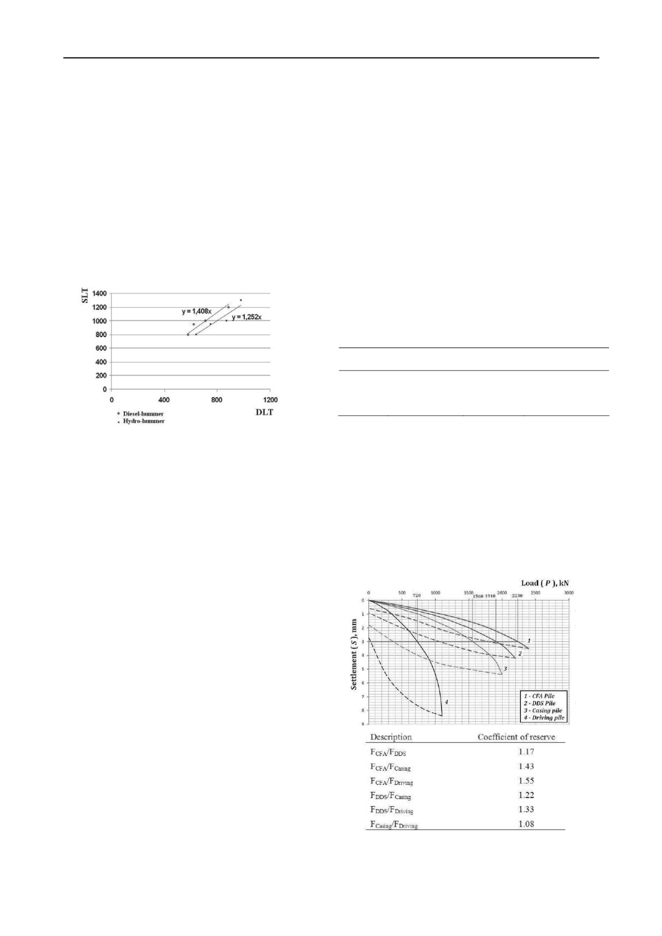
Results of comparison are presenting in Figure 5.
All of these coefficients show incapacity of accurate design
of modern pile technology by out-of date Standards, otherwise
this coefficients tending to 1. The results of SLT showed
entirely expected regularity. CFA piles showed highest bearing
capacity as long as during CFA pile installation it was expended
much more concrete (in 2 times) than during casing pile
installation. This factor was not considered during design;
therefore coefficient equal 1.43. DDS pile approved effluence of
compacted soil; therefore coefficient equal 1.22 (DDS versus
casing). Differences between driving and casing pile neglected
small, the reason of differences is empirical coefficients
required by Standards.
Figure 5. Bearing capacity comparison of different piles


