2692
Proceedings of the 18
th
International Conference on Soil Mechanics and Geotechnical Engineering, Paris 2013
2 EXPERIMENTAL BACKGROUND
The vertical vibration tests on the full-scale single pile were
conducted at I.I.T. Kharagpur Extension Centre, Block No. HC,
Plot. 7, Sector - III, Salt Lake City, Kolkata, India (Manna and
Baidya, 2009). In the field three bore holes were made and soil
samples were collected. The depth of exploration below ground
level was 30.45 m. Disturbed representative soil samples and
undisturbed soil samples were collected from the field. During
boring ground water was encountered in all the three boreholes
and it was found that the position of standing water table was at
1.25 m below the ground level. Standard penetration tests (SPT)
were carried out in the field and the SPT -
N
value was
determined at different depths of the soil strata. Based on
different laboratory observations and field test results the site
soil was divided into six different layers. The RCC piles were
constructed at site using cast in situ technique. The diameter and
length of the pile were 0.45 m and 22 m respectively. Forced
vibration tests were conducted on the piles in vertical direction.
The mechanical oscillator (Lazan type) was used to induce
unidirectional vibrations on pile foundation. The mechanical
oscillator was connected by means of a flexible shaft with a
motor and its speed was controlled by a speed control unit. The
vibration measuring equipment consisted of a piezoelectric
acceleration pickup and the associated vibration meter. The
complete dynamic test set up is shown in Figure. 1. The
amplitudes were measured at different frequencies for each
eccentric setting. Tests were conducted for four different
exciting moments (0.278, 0.366, 0.45, and 0.529 Nm) under
different static loads (8 kN and 10 kN).
Figure. 1 Complete setup of vertical vibration test on full-scale pile
3 THREE DIMENSIONAL FINITE ELEMENT
MODELLING
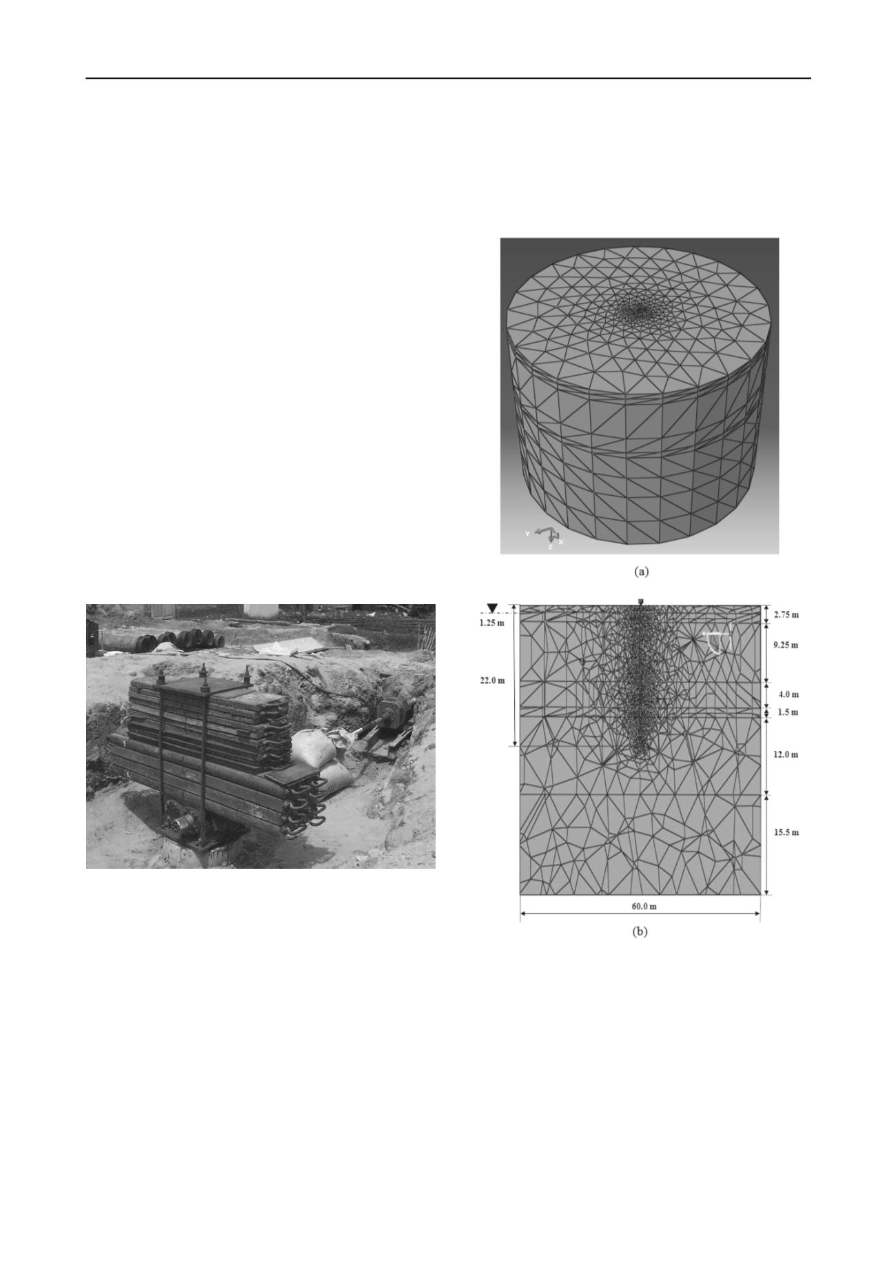
A 3-D FE model was developed to study the nonlinear soil-pile
interaction using the finite element software, ABAQUS/CAE
6.11 (2010). A harmonic vibration load was applied i.e., rotating
mass type machine at the top of a 0.45 m diameter single pile
having 22 m length. Both the pile and soil mass were meshed
using tetrahedral solid elements (10 nodded) where elements
were more closely spaced near the pile compared to the outer
region shown in Figure. 2(a). Boundary conditions were applied
to those regions of the model where the displacements and/or
rotations were known. Bottom soil boundary nodes were
considered as fixed against displacements and rotations at all
directions. At the side soil boundary, nodes displacement and
rotation were allowed only in vertical Z direction.
The soil-pile interaction was modelled using surface-to-
surface contact algorithm, where relative movement between
soil and pile was allowed for considering friction. The
tangential contact between the pile and the surrounding soil was
defined using Coulomb's Law with a friction coefficient
estimated by the tangent of the friction angle between the two
materials. The normal behaviour was considered to be hard (no
penetration to each other) allowing separation after contact.
Figure 2. Three Dimensional Finite Element Model of Soil-Pile System:
(a) 3-D view and (b) Sectional view.
The whole system was modelled in six layers of soil as
found in site investigation (Manna and Baidya, 2009) and the
sectional view of the model is shown in Figure. 2(b). The
phreatic level was considered 1.25 m below the ground surface
and the effective soil pressure was applied in the whole
geometry according to this phreatic line. Soil behaviour was
considered as elasto-plastic. The displacement of soil had both a
recoverable and non-recoverable component under load.
Therefore, there was a need to include a failure criterion in the
elastic models to define the stress states that would cause the
plastic deformation. Mohr-Coulomb model was adopted for soil
to simulate the elasto-plastic behaviour. For analysis the FE
model material damping was considered. The Rayleigh damping


