3044
Proceedings of the 18
th
International Conference on Soil Mechanics and Geotechnical Engineering, Paris 2013
Key design considerations and aspects of the design and life
cycle of the PRBs included the panel and gate widths, reactive
media and treatment process, hydrogeology, contaminant
distribution, geochemistry; reaction kinetics and residence time;
and installation methods. The ratio of panel width to gate width
was selected as 6:1 following groundwater modelling of flows
and residence times through the gates.
Table 1. Summary of Selected Remediation Options
Contamination Issue
Preferred
Remediation
Option
Second
Ranked
Option
Third
Ranked
Option
Pond 5/7 tar waste
Barrier Wall
Permeable
Reactive
Barrier
Cap and
Monitor
Lead Dust /
Asbestos
Permeable
Reactive
Barrier
Barrier Wall
Interception
Drain and
Monitor
Free Phase LNAPL
Multi Phase
Extraction
Pump and
Treat
Barrier Wall
Fines Disposal
Facility
Permeable
Reactive
Barrier
Cap and
Monitor
Interception
Drain and
Monitor
Manganese Dioxide
area (EMD) -
Dredging Phase
Liner (GCL)
prior to
dredging
Barrier Wall
Interception
Drain and
Monitor
It is also proposed to extend the wall as a continuous low-
permeability barrier to the west, adjacent to a surface water
body now as Deep Pond to protect the wetlands to the west and
north from the saline water during dredging.
5.4 Free Phase Hydrocarbon Area
The preferred remediation option for the free-phase LNAPL
contamination is multi-phase extraction (MPE). MPE is an in-
situ remediation technology for simultaneous extraction of
vapour phase, dissolved phase and separate phase (e.g. LNAPL)
contaminants from the vadose zone, capillary fringe, and
saturated zone soils and groundwater. It will likely be followed
by monitored natural attenuation (MNA) for residual dissolved
phase hydrocarbon contamination.
5.5 Manganese Dioxide Waste Area
5.2 Tar Waste Ponds
The soil-bentonite barrier wall enclosing the Pond 5/7 tar waste
would be approximately 1 km long and 10 m deep, keyed into
the clay aquitard. The design of the wall will take into account
the hydraulic conditions of the contained volume under initial
loading (especially preload), which would be a one-off event
during construction. Key design issues for the barrier wall were:
The preferred remediation option to manage risks associated
with dredging activities within the manganese dioxide waste site
is to install a low-permeability geo-synthetic clay liner (GCL)
over the site prior to dredging.
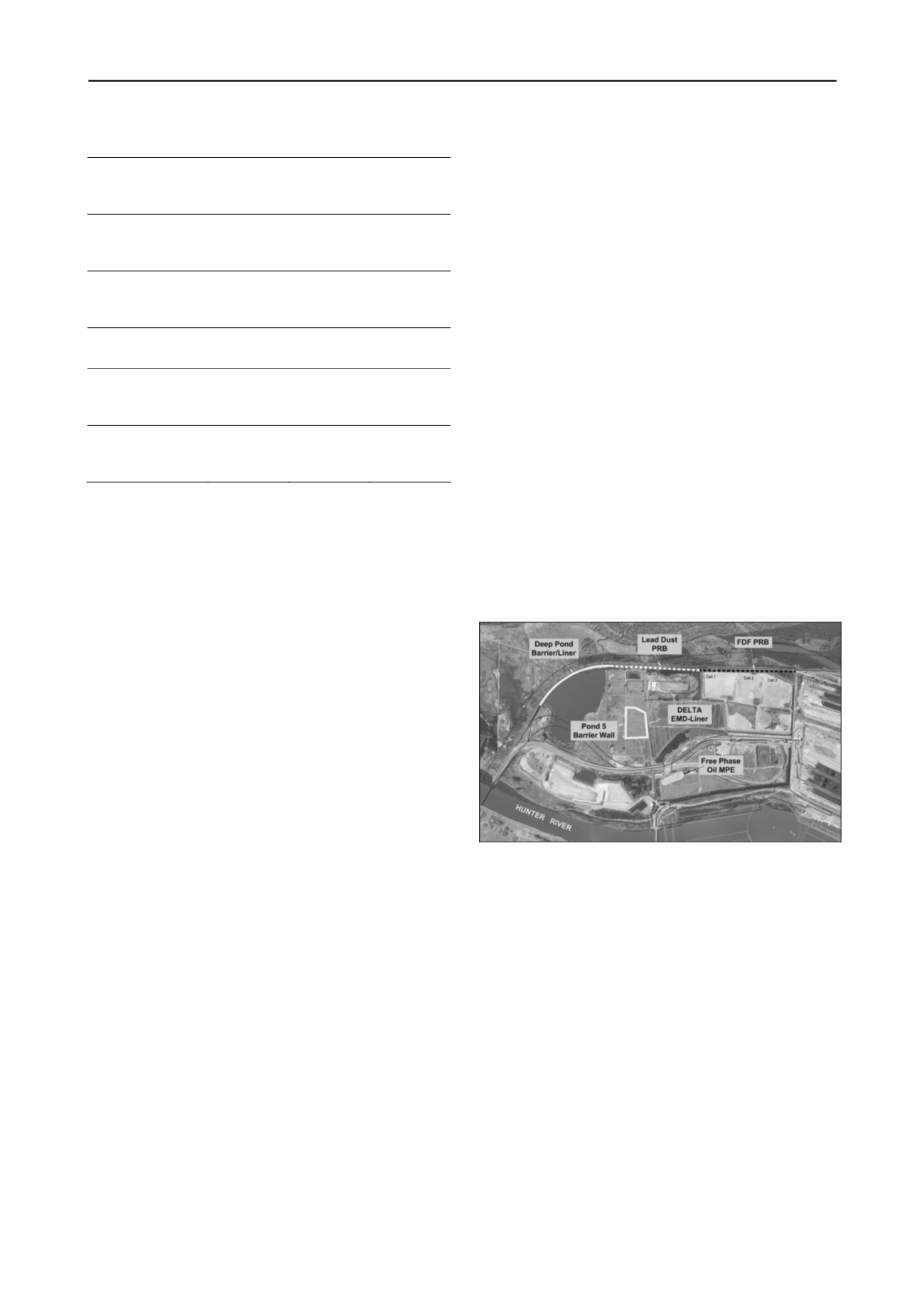
An overall plan showing the location and extent of the
preferred remediation options is presented in Figure 3.
Pre-trenching through the existing slag cell walls and other
cemented layers in the fill for slurry trench construction;
Mix Design of the bentonite slurry, including compatibility
with site groundwater and soil conditions;
Mix design of the soil-bentonite backfill, including
compatibility with site groundwater and soil conditions;
Global and local stability of the slurry trench;
Density and viscosity of the slurry and backfill materials,
such that trench stability is maintained, while permitting the
backfill to displace the slurry; and
Provision of vertical drainage (e.g. wick drains or sand
drains) internal to the enclosed barrier wall to control pore
pressures generated during preloading.
Figure 3. Remediation Plan.
6 CONCLUSIONS
5.3 Asbestos / Lead Area and Fines Disposal Facility
The ‘precautionary principle’ was applied to the potential risk
resulting from the asbestos/lead dust area. The permeable
reactive barrier (PRB) would be designed to maintain northerly
groundwater flows while ‘treating’ lead leachate in the event
that lead dust comes into contact with the groundwater.
The PRB at the fines disposal facility would also be designed
to maintain northerly groundwater flows while ‘treating’
leachate potentially generated by dredged sediments coming
into contact with the groundwater. The target contaminants are
metals (mainly aluminium) and PAH.
The two PRBs will be a ‘funnel and gate’ type comprising
‘gates’ of reactive medium with intervening panels of
impermeable barrier wall. This system allows for more
convenient maintenance and, if needed, replenishment of the
reactive media. The Operational Environmental Management
Plan for the terminal will incorporate regular monitoring and
maintenance of the reactive media.
The Terminal 4 Project is planned to be constructed at a site that
presents complex geotechnical and environmental conditions.
The investigation required close integration of geotechnical,
contamination and groundwater assessments. The project will
beneficially re-use a highly degraded site by implementing
several remediation measures on a large scale, making the
project unique to Australia and unusual worldwide. The method
of selecting the preferred remediation options is described, and
the key design considerations discussed. The Terminal 4 Project
is expected to improve the long-term environmental condition
of a site previously contaminated by industrial waste, while
protecting the surrounding sensitive environment.
The PRBs will be installed along the northern boundary of
the site and keyed into the clay aquitard at a depth of about 4 m
to 5 m.
7 ACKNOWLEDGEMENTS
The author thanks Port Waratah Coal Services Limited for
providing permission to publish this paper. The staff at Douglas
Partners’ Newcastle office is acknowledged for their hard work
and commitment to this important and complex project.


