3047
Technical Committee 215 /
Comité technique 215
Bund failure has never occurred at the site. Therefore, it can
be inferred that the undrained shear strength of the sludge
material is higher than the back-analysed undrained shear
strength envelope (assuming a safety factor of unity). The back-
analysed shear strength envelopes (refer Figure 1) show that the
Geonor vane and triaxial undrained shear strength data closely
fit the back analysed shear strength envelope for a safety factor
of 1.1 and is therefore more representative of the sludge
undrained shear strength characteristics.
3.3.3
Pore pressure monitoring
Six pore water pressure transducers were installed in two
boreholes at various depths below the ground surface. Pore
water pressures were measured over a period of one month.
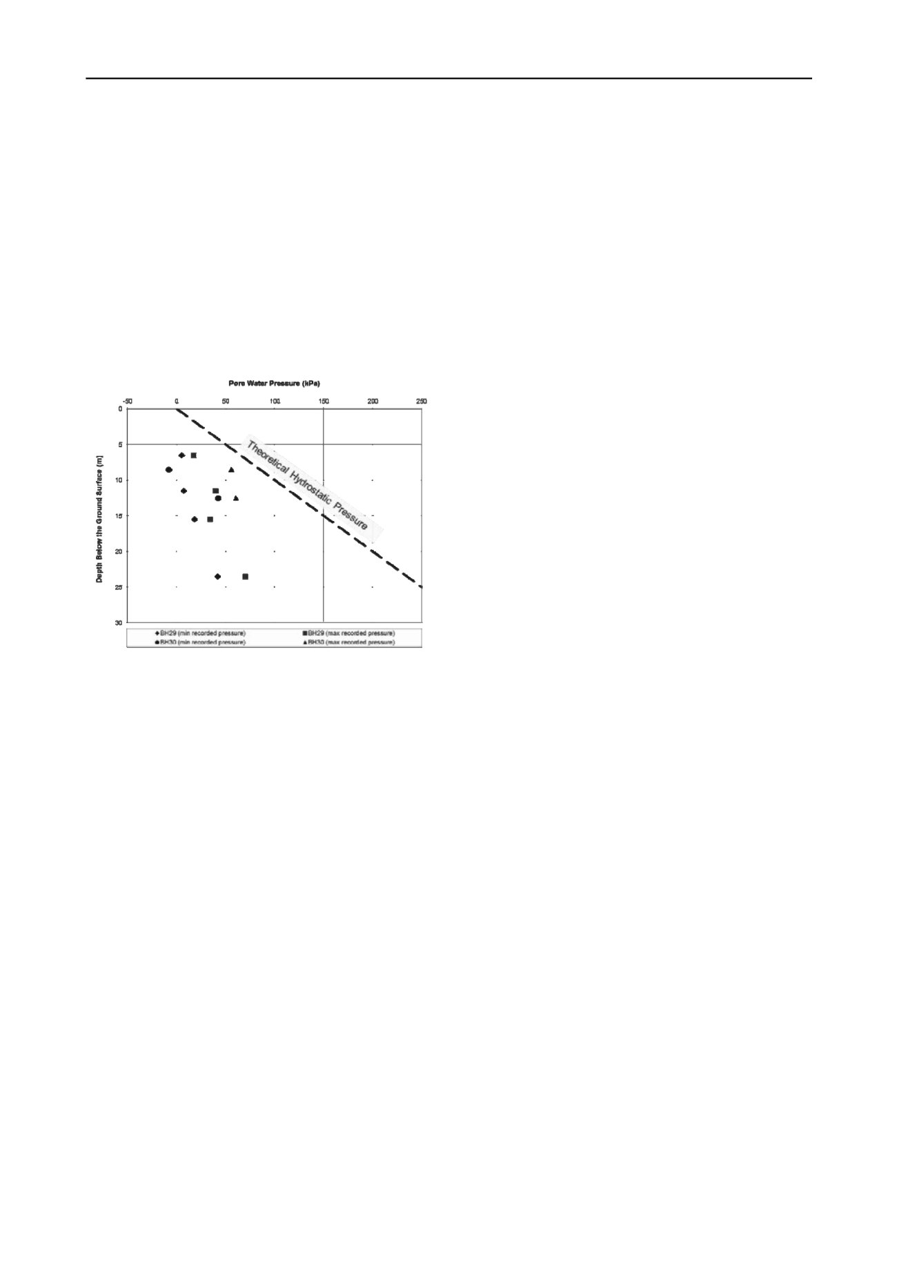
Figure 2. Pore water pressure distribution in sludge with depth
The sludge pore water pressure monitoring results are
presented in Figure 2. The maximum and minimum ground
water pressures measured by the transducers are presented as a
function of depth below the ground surface. The results indicate
that the pore water pressures in the sludge material range from
10kPa to 60kPa and are significantly lower than the theoretical
pore water pressures for hydrostatic conditions with the water
table at the ground surface. These results demonstrate the sludge
mass is able to dry out and desiccate prior to subsequent
placement of the above sludge layers and that the sludge mass is
able to drain within the landfill cells.
4 LIQUEFACTION
The assessment of liquefaction potential of the sludge waste has
been approached using CPT data and Atterberg Limits.
4.1
CPT-based liquefaction assessment
Liquefaction analyses using the CPT data have been undertaken
using the assessment methods developed from the 1998
NCEER/NSF Workshop, supplemented and updated with the
more recent recommendations for liquefaction assessment
including the works of Zhang et al. (2002), Cetin et al. (2004),
Moss et al (2006a), and Moss et al. (2006b).
The CPT data show that the sludge materials are very
cohesive (i.e. they have Ic values greater than 2.6) and
therefore, in theory, are not susceptible to liquefaction. The
calculated liquefaction factor of safety (derived from CRR
7.5
)
for the majority of the CPT data was above 1.0 for a peak
ground acceleration of 0.17g (10% probability of exceedance
for a 30 year period).
4.2
Liquefaction Susceptibility using Atterberg limits
Over the past few decades it has been assumed that fine-grained
soils (silts and clays) do not liquefy. Recent research has shown
that, under some circumstances, fine grained soils (such as
sludge) may be susceptible to liquefaction and there have been
various suggested criteria for defining the limits.
Seed et al. (2003) recommended an area on the Casagrande
Plasticity Chart within which soils should be classified as
“potentially liquefiable”. Out of nine, eight results are all well
outside the potentially liquefiable region. Therefore the waste
mass as a whole is not susceptible to liquefaction according to
these criteria. Some small pockets or zones may be more
susceptible than others, but will not govern the behaviour of the
overall material mass.
Bray & Sancio (2006) suggested criteria based on PI and the
ratio of natural water content to the liquid limit (w/LL). Again,
only one result out of nine plots within the “Susceptible” region.
Boulanger & Idriss (2006) suggested that materials can be
expected to exhibit clay-like behaviour ( i.e. non liquefiable) if
they have PI value of greater than 7 and that fine-grained soils
with PI values less than 7 should be considered as potentially
exhibiting “sand-like” behaviour (i.e. liquefiable). The PI data
for the sludge range from 10 to 53 and fall into the “clay-like”
category, indicating the material is not susceptible to
liquefaction.
4.3
Liquefaction conclusion
It is concluded that the landfill materials are not susceptible to
liquefaction under any credible level of shaking. In addition to
this, however, it should be noted that the level of shaking under
operating conditions (10% probability of exceedance in 5 years)
is only 0.06g, and this is unlikely to exceed the strain threshold
for liquefaction to occur for any type of material, except very
loose sands.
In the long term the final landfill geometry will have a
maximum slope of 5H: 1V and will be made up of consolidated
sludge in many separated cells with numerous effective RPCC
“chimney drains” extending up full-height through the fill.
Even if liquefaction could occur, it would be localised and
confined within the cells, with little risk of significant
displacement.
5 DESIGN
Based on in situ and laboratory testing at the West Landfill, the
sludge design parameters that have been selected for the cell
design of the East Landfill are summarised in Table 1.
A seismic reduction factor was adopted for the sludge shear
strength envelope to account for potential cyclic strain softening
that may occur within the sludge during seismic loading. For a
7.5 magnitude earthquake, Boulanger and Idriss (2007)
recommend a ratio of cyclic undrained to static strength for
natural clays/silts is 0.8. Therefore the static strength was
reduced by 20%.
Table 1. Sludge design parameters used for design of East Landfill
Test Method
Undrained
Drained


