2931
Technical Committee 214 /
Comité technique 214
c
avg
= (1 -
a
s
)
c
(5)
avg
= tan
-1
(μ
s
a
s
tan
s
)
(6)
3.2 Stability Analysis
The stabilityanalyses of the stone column seawall were carried
out using the computer software “Slope/W” with automatic
circular failure mode and sliding block failure modes. The stone
column foundation was modelled as a composite material with the
embankment of landfill in place behind the seawall(Figure 6).
With
a
s
of about 21%, the average cohesion of the composite
material immediately after placing the stone columns will range
from 2.8 kPa to 12.7 kPa; and the average friction angle of the
composite material is 20.4°.
Fill (0, 33)
Original sea bed
at ~-0.5MCD
MD6 kPa
MD3.5kPa
MD9.5kPa
MD16kPa
1.2m diameterStone Column
at 2.5mTrianglarPattern
Alluvium (4, 28)
LowTide
at +0.5MCD
Stone Column (c=2.8 kPa, o'=20.4°)
Stone Column (c=4.8 kPa, o'=20.4°)
Rockfill
(0, 40)
Stone Column (c=7.5 kPa, o'=20.4°)
Stone Column (c=12.7kPa, o'=20.4°)
10kPa
FormationLevel
ofseawall
at about +3.5 MCD
10kPa
Mud Spoil
1.5kPa
MD3.5kPa
MD6 kPa
MD9.5kPa
MD16kPa
FormationLevel
for landfill at about +7.5MCD
BaseofMD
at about -14.9MCD
-30 -25 -20 -15 -10 -5 0 5 10 15 20 25 30 35 40 45 50 55 60 65 70 75 80
Elevation (mCD)
-25.0
-22.5
-20.0
-17.5
-15.0
-12.5
-10.0
-7.5
-5.0
-2.5
0.0
2.5
5.0
7.5
10.0
Figure 6. Geological Model for Slope Stability Analyses
To maintain the seawall stability, a 50m wide stone column
treatment zonewas required. The seawall revetment and the
landfill embankment slope profileswere proposed at a gradient of
1V:2H. A toe bund is provided as counterweight to stabilise the
rockfill revetment. A typical section is shown in Figure 7.
Figure 7. Typical Cross Section of
the Seawall
The stone columns will also act as vertical drains to provide
drainage path for the excess pore water pressures arising from
the vertical load of the embankment. With a typical 15 m thick
marine deposit and an equivalent rectangle embankment width
of about 30 m, the average increase in the effective stress of
Marine Mud is only 25 kPa. Based on the radial consolidation
theory and settlement reduction by the stone columns, 0.6 m
settlement will occur within a year. Due to uncertainty in the
drainage performance of the stone columns, the increase in the
strength of the marine clay as a result of consolidation was not
taken into account in stability analyses.
3.3 Assessment of Impact on Taxiway Pile Foundation
Since the STB is a critical facility to the MIA any damage to the
STB will significantly affect the operation of the MIA. In order
to control the additional load imposed from landfill site to the
STB, numerical modelling was carried out to assess the impact
to the STB during installation of the stone columns,
construction of the seawall and when filling behind the seawall
as part of the landfilling operation.
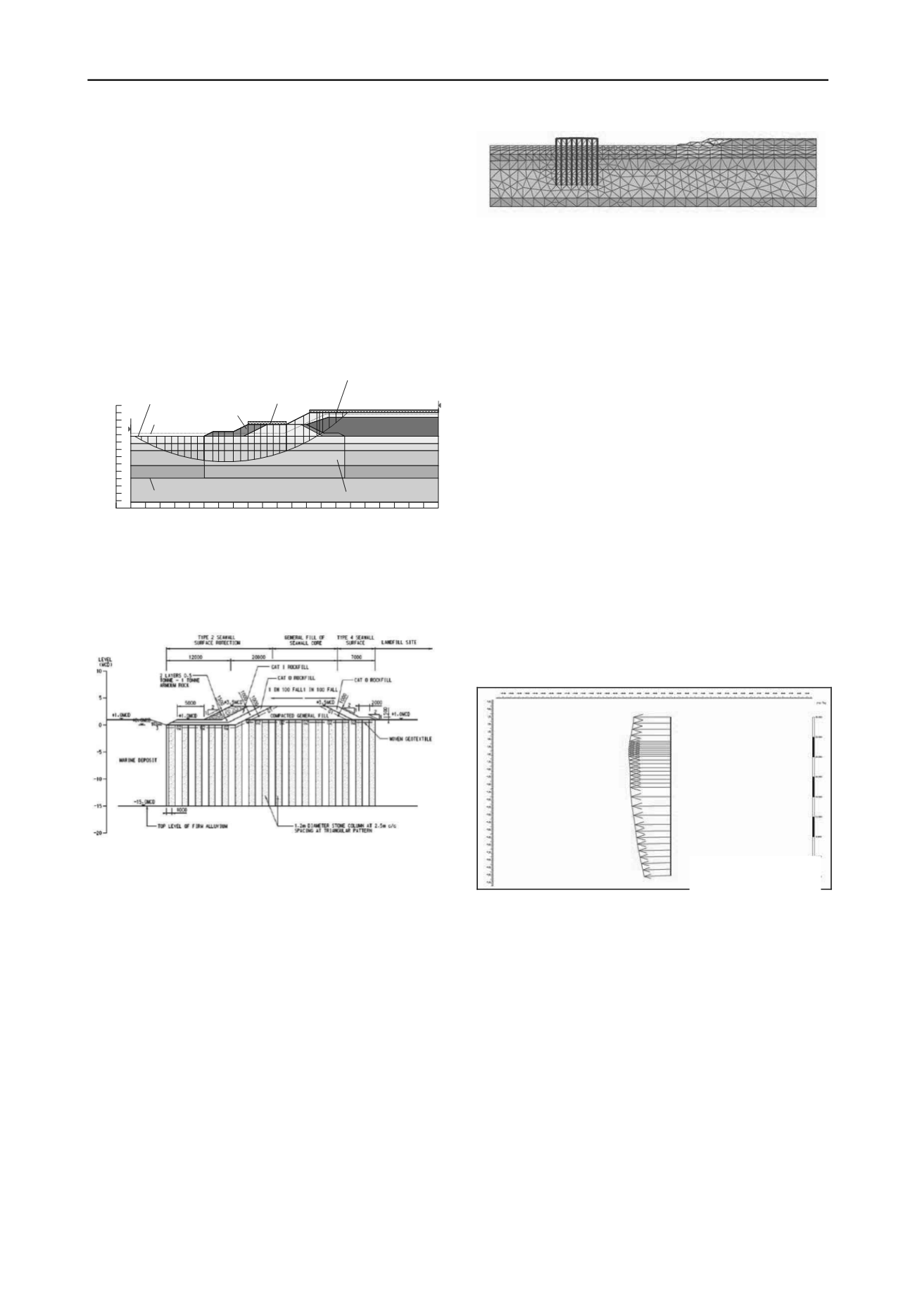
Figure 8. Finite Element Model
A Finite element model was developed (see Figure 9) using
PLAXIS. The model adopted a geological profile with the
deepest seabed level and thickest alluvium of the entire length
of the seawall. The analyses were carried out with the marine
clay behaving as an undrained material, which is considered to
be an appropriate approach to model the actual behaviour of the
soft clay. The structural elements included the beams and the
PHC piles of the STBwere modelled as a continuous beam/wall
element in the PLAXIS modelwith an influence zone of 3 times
the diameter being adopted (LECM 2008b). The model
simulates the full history of the site including the original
ground conditions, formation of the STB, installation of the
stone columns, formation of the seawall and landfilling
operation behind it.
The results from numerical modeling show that the
maximum additional bending moment due to stone column
installation, seawall construction and landfilling activities is
only 6 kNm near the top of the STB piles and the total load of
the pile is still within the acceptable limit of the original design.
The additional shear force is considered to be not significant.
The maximum predicted movement of the nearest piles to the
seawall is about 8 mm (Figure 9). This predicted lateral
movement is likely to span across a few spans of the taxiway
and the actual magnitude of relative movement between each
span of taxiway structure is unlikely to be a concern
asmovement joints have been provided between the taxiway
spans and it should be capable of withstanding this relative
movement.
Figure 9. Predicted lateral Displacement of the Taxiway Foundation
Total displacement
Extreme 7.95*10
-3
m
3.4 Construction
Since the site is situated close to the MIA, there are certain
physical constrains imposed by the Civil Aviation Authority of
Macau on construction activities. The entire site is within the
navigation restriction zone of the MIA (Figure 10). Marine
access to the site is restricted and no mooring of vessels was
allowed within the navigation restriction zone around the
Airport. To avoid any disturbances on the movement of aircraft
along the STB, all works were required to be carried out outside
a zone of 57.5m from the centreline of the STB. Based on the
information from the Civil Aviation Authority of Macau
(AACM), the height restriction in the vicinity of the MIA along
the runway is stringent and the use of high cranes was restricted.
As a result, dredged seawall was adopted near the eastern end of
the seawall.


