 
          2930
        
        
          Proceedings of the 18
        
        
          th
        
        
          International Conference on Soil Mechanics and Geotechnical Engineering, Paris 2013
        
        
          2 SITE GEOLOGY
        
        
          The superficial deposits within the study area comprise marine
        
        
          deposit (MD) of the Holocene age overlying a layer of alluvium
        
        
          of the Pleistocene age. Underlying the alluvium is the saprolitic
        
        
          soil consisting of completely decomposed granite (CDG). The
        
        
          solid geology comprises coarse-grained granite of Jurassic-
        
        
          Cretaceous age.  Fill material has been subsequently placed over
        
        
          the marine soft clay deposit by the landfilling activities.
        
        
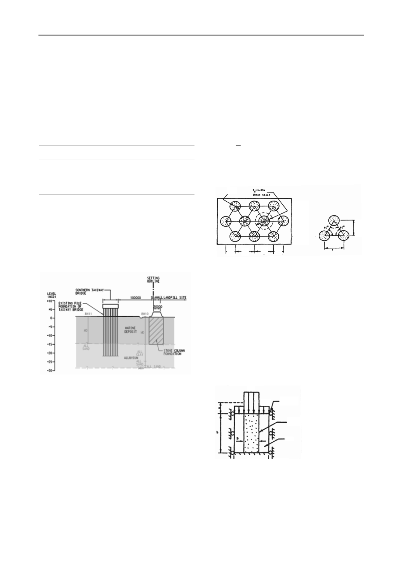
          Figure 3 shows the typical geological section of the site. Table 1
        
        
          shows the typical thickness and constituentcy of the strata.
        
        
          Table 1. Summary of Geological Strata
        
        
          Strata
        
        
          Thickness
        
        
          (m)
        
        
          Constituent
        
        
          Fill
        
        
          4 to 7
        
        
          C&D waste comprised disturbed mud, silty
        
        
          clayey, sand, concrete, bricks, wood, steel
        
        
          Marine
        
        
          Mud
        
        
          13 to 28
        
        
          Very soft to soft, dark grey, clay to silty
        
        
          clay with occasional shell fragments.
        
        
          Alluvium
        
        
          0 to 58
        
        
          average
        
        
          30
        
        
          Soft to stiff, mottled yellowish brown light
        
        
          grey to brown, silty CLAY, CLAY/SILT
        
        
          Medium dense to very dense, yellowish
        
        
          brown to yellowish grey, silty fine to
        
        
          coarse SAND.
        
        
          CDG
        
        
          0 to 10
        
        
          Sandy silty to silty fine to coarse SAND
        
        
          Bedrock
        
        
          -
        
        
          Moderately strong to strong, moderately
        
        
          to slightly decomposed granite.
        
        
          Figure 3. Typical Geological Section
        
        
          3 DESIGN OF THE SEAWALL
        
        
          The purpose of the seawall is to contain the dumped surfical
        
        
          clayey and other materials from spreading towards the STB, to
        
        
          prevent the further generation of the mudwaves that would
        
        
          impact the STB and to provide a stable and secure edge to the
        
        
          landfill.  Since the founding material of the seawall is very soft
        
        
          to soft marine clay, ground treatment, by means of stone
        
        
          columns, are required to strength the foundation of the seawall
        
        
          in order to ensure the stability.  It also improved the shear
        
        
          strength and stiffness of the soil mass to minimise the influence
        
        
          of the lateral load induced by the landfill soil mass that could
        
        
          possibly cause disturbance to the STB.


            3.1 Principle of Ground Improvement by Stone Column


          Stone column construction involves the partial replacement of
        
        
          the very soft subsurface soils with compacted, vertical columns
        
        
          of stone that completely penetrates the weak strata. The stronger
        
        
          and stiffer material will attract more stresses (i.e. the stone
        
        
          columns) and therefore the composite ground comprising stone
        
        
          columns and soft clay (Barksdale, R.D. & Bachus R.C. 1983)
        
        
          will be stronger and stiffer and capable of carrying a larger load
        
        
          originating from the landfill behind,preventing the formation of
        
        
          mudwaves. The stone columns will also act as vertical drains
        
        
          within the soft clay facilitating the rapid dissipation of the
        
        
          excess pore pressures allowing it to quickly consolidate and
        
        
          gain in strength, thus further increasing the stiffness of the
        
        
          composite soil mass over time.
        
        
          The strength of the composite ground depends on the
        
        
          percentage of soil replaced by the stone columns, i.e. the
        
        
          replacement ratio,


            a


            s


          , as defined by (1) and illustrated in Figure 4.
        
        
          2
        
        
          1


            s


            DC a


            s


          (1)
        
        
          D -
        
        
          Diameter
        
        
          of the compacted stone column
        
        
          s
        
        
          - Centre to centre spacing of stone columns
        
        
          C
        
        
          1
        
        
          - Constant
        
        
          depending
        
        
          on stone column configuration pattern


            D


            s/2 s


            s/2 s


          Figure 4. Replacement Ratio of Stone Columns
        
        
          For this project, a 1.2 m diameter stone column at 2.5 m c/c
        
        
          spacing in a triangular pattern was adopted.  The replacement
        
        
          ratio


            a


            s


          is about 21%. Since the stone aggregate columns are
        
        
          much stiffer than the soft clay, the stresses will concentrate at
        
        
          the stone columns. The distribution of the stresses can be
        
        
          expressed by the stress concentrated factor


            n


          , defined as:


            c


            s


            n


          (2)


            σ


            s


          = stress in the stone column


            σ


            c


          = stress in the surrounding cohesive soil
        
        
          The stresses over the soft soil and the stone column in term
        
        
          of


            a


            s


          from (1) and the average overall stress on the ground
        
        
          surface,


            σ,


          is illustrated in a unit cell concept in Figure 5.
        
        
          0.866s


            σ


            s


          Fictitious
        
        
          roller


            σ


            c


          Stone
        
        
          column


            σ


            s


          - Stress in stone
        
        
          Soil


            σ


            c


          -Stress in clay
        
        
          Figure 5. Ideal Unit Cell of Stone Column


            σ


            s =


            n σ / [1+(n-1) a


            s] =


            μ


            s


            σ


          (3)


            σ


            c =


            σ / [1+(n-1) a


            s] =


            μ


            c


            σ


          (4)


            μ


            s


          =Ratio of stress in stone in relation to


            σ


            μ


            c


          = Ratio of stress in cohesive soil in relationto


            σ


          Using the expression of


            μ


            s


          in (3), the stone column
        
        
          foundation can be modeled as a composite material with the
        
        
          average shear resistance expressed as: