 
          2938
        
        
          Proceedings of the 18
        
        
          th
        
        
          International Conference on Soil Mechanics and Geotechnical Engineering, Paris 2013
        
        
          improvement took place (2006), cement prices were
        
        
          significantly higher because of global demand, and the
        
        
          estimated cost for the DSM option was estimated to be $150
        
        
          million (2011 US dollars).
        
        
          2 PREFABRICATED VERTICAL DRAINS FEASIBILITY
        
        
          STUDY
        
        
          Installation of prefabricated vertical drains (PVDs) is a cost-
        
        
          effective foundation improvement technique at sites where a
        
        
          surcharge load will be applied (e.g., an MSE berm).  In general,
        
        
          PVDs are installed in soft soils to improve the drainage
        
        
          characteristics hence accelerating the dissipation of excess pore
        
        
          pressures generated during stage construction of embankments.
        
        
          The time it takes for pore pressures to dissipate depends upon
        
        
          the permeability of the dredge and the spacing between PVDs
        
        
          and it can be estimated using well known radial flow equations
        
        
          (e.g., Barron, 1948).
        
        
          Initially, the use of PVDs to improve the foundation
        
        
          strength appeared unfeasible due to the massive weight of the
        
        
          proposed 21-m high MSE berm which was required to gain the
        
        
          needed airspace. Typically, the maximum height of an MSE
        
        
          berm on soft soils is dictated by the undrained shear strength of
        
        
          the underlying soft material.  At the CIL site, the maximum
        
        
          height that could have been built using standard design
        
        
          techniques would have been on the order of 7.5-m (i.e., about
        
        
          13.5 m shorter than required to achieve the target airspace of 17
        
        
          million cubic meters).
        
        
          Standard design techniques assume that when PVDs are
        
        
          installed in soft soils: (i) the excess pore pressures generated
        
        
          between PVDs during loading is uniform; and (ii) only
        
        
          undrained shear strength is mobilized during loading. The
        
        
          maximum excess pore pressures (


            U


            max


          ) generated after
        
        
          placement of a soil lift (i.e., 3 m for the CIL project) is
        
        
          estimated assuming that the soil lift is placed at once and it
        
        
          generates excess pore pressures (i.e., the pressure of the water
        
        
          stored within the dredge) approximately equal to the weight of
        
        
          the soil lift.  Although it is recognized that excess pore pressures
        
        
          at the PVD location is nil and increases with radial distance
        
        
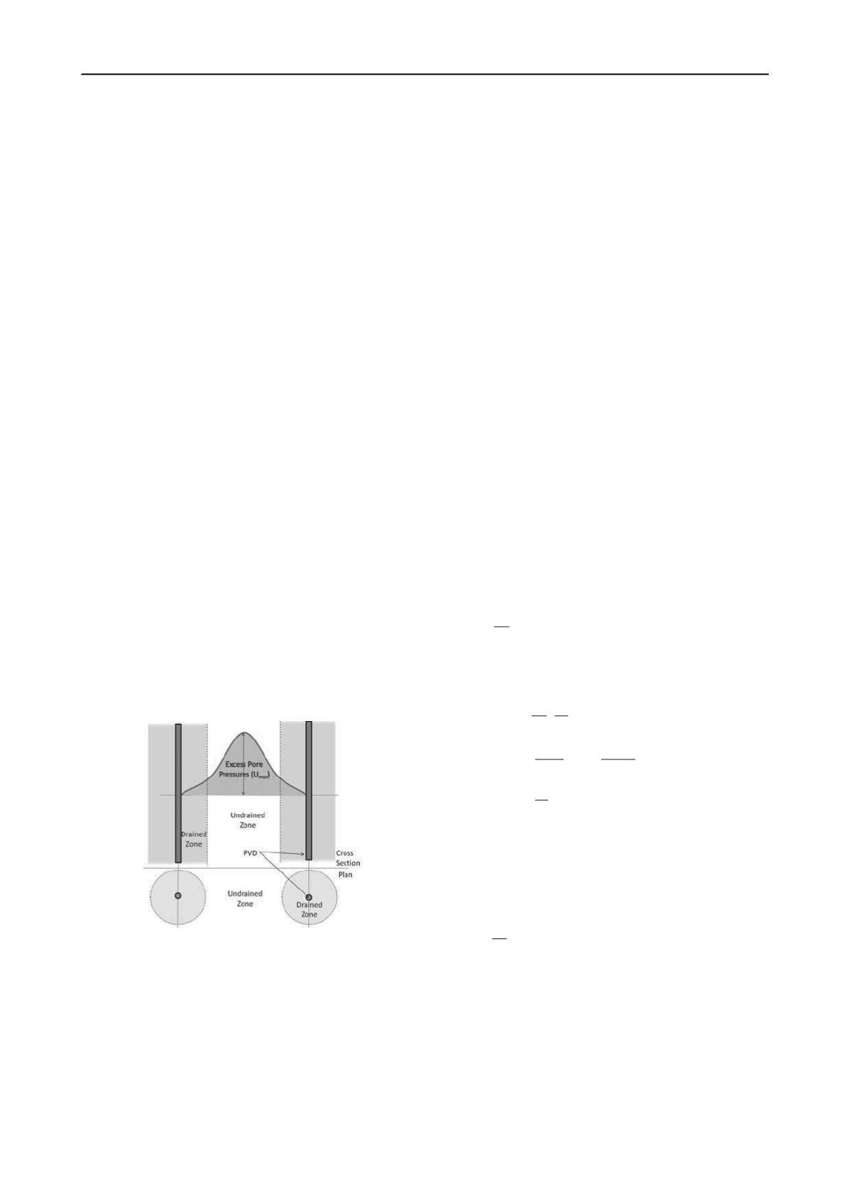
          from the PVD (Figure 2), it is typically assumed that excess
        
        
          pore pressures between PVDs are uniform and equal to


            U


            max


          .
        
        
          Figure 2. Pore Pressure Model
        
        
          Because piezometers are located to monitor the maximum
        
        
          pore pressure, the radial variation is usually neglected.
        
        
          However, this conservative assumption made for computation
        
        
          and monitoring expedience not only neglects the fact that the
        
        
          excess pore pressures is not uniform but also does not take into
        
        
          consideration how PVDs change the dredge response to loading.
        
        
          In theory, drained parameters could be used to represent the
        
        
          shear strength of soft soils with PVDs if the applied loads (i.e.,
        
        
          construction of the MSE berm) are imposed slowly enough to
        
        
          allow all excess pore pressures to dissipate as loading takes
        
        
          place. In practice, this could not be implemented because the
        
        
          rate of loading would need to be too slow to be feasible.
        
        
          3 VIRTUAL SAND PILES: HYBRID DRAINED-
        
        
          UNDRAINED MODEL
        
        
          The centerpiece of innovation for the design and construction of
        
        
          this massive MSE berm was the improvement of the weak
        
        
          dredge/alluvium foundation material using the concept of
        
        
          ‘virtual sand piles’, also described as the Hybrid Drained-
        
        
          Undrained (HDU) model (Espinoza et al., 2011).
        
        
          The virtual sand pile concept is illustrated Figure 2. As
        
        
          shown in this figure, the closer the dredge is to the PVD the
        
        
          smaller the generated excess pore pressure and the faster that
        
        
          are dissipated. Hence, depending upon the speed of
        
        
          construction, it can be assumed that there are two distinct zones
        
        
          with different shear strength characteristics during loading: a
        
        
          drained zone, near the PVDs, and an undrained zone further
        
        
          from the PVDs.  This concept constitutes a significant departure
        
        
          from standard design of soft cohesive soils with PVDs and it is
        
        
          the central element of the design. The development of the novel
        
        
          HDU design methodology for PVD design, to analyze the
        
        
          strength characteristics of the soft foundation soils during
        
        
          construction made the use of PVDs feasible for the CIL Project.
        
        
          Subsequently, a more realistic model was developed to
        
        
          consider that: (i) the soils located closer to PVDs dissipate
        
        
          excess pore pressures generated during construction to more
        
        
          quickly than the soils located farther away from PVDs (Figure
        
        
          2); and (ii) the rate of construction influences the maximum
        
        
          excess pore pressure that could be generated (i.e., pore pressures
        
        
          dissipate as the soil lift is placed).  To simplify the model
        
        
          development, the rate of berm placement construction was
        
        
          assumed constant and equal to


            R


            c


          . For each lift of soil, it was
        
        
          assumed that excess pore pressures starts to dissipate soon after
        
        
          it was placed (see Figure 3).  Assuming an exponential decay
        
        
          function, the resulting excess pore pressure equation as a
        
        
          function of time is:


            p


            t


            c


            t t


            e R tu


          for
        
        
          1 )(


          (1)
        
        
          where:


            t


            p


          is the time that takes to place the fill and


          is a
        
        
          parameter that is related to Barron’s Equations (1948)
        
        
          developed for sand drains:


          2
        
        
          2


            i


            v


            n


            r


            c


            F


          (2)
        
        
          2
        
        
          2
        
        
          2
        
        
          2
        
        
          4
        
        
          1 3 ) ln(
        
        
          1


            n


            n n


            n


            n F


            n


          (3)


            e


            i


            r


            r n


          (4)
        
        
          and


            c


            v


          is the coefficient of consolidation;


            r


            i


          is the radius of
        
        
          influence of the PVDs; and


            r


            e


          is the equivalent radius of the
        
        
          PVD.  The maximum pore pressure takes place at


            t


          =


            t


          p
        
        
          . It
        
        
          follows that after fill placement, it is assumed that excess pore
        
        
          pressure dissipates according to the same decay function, then:


            p


            t t


            t


            c


            t t


            e e R tu


            p


            p


          for
        
        
          1 )(
        
        
          )
        
        
          (


          (5)
        
        
          4 SELECTING THE DIAMETER OF THE VIRTUAL
        
        
          SAND PILE
        
        
          Equations (1) through (5) were used to select the appropriate
        
        
          PVD spacing along with the corresponding rate of construction
        
        
          such that the soils near the PVDs would generate significantly
        
        
          smaller pore pressures that would allow to model the dredge
        
        
          around the PVD as a virtual sand pile. This meant that these
        
        
          soils could be considered to have a drained response during
        
        
          loading. The modified procedure consists of selecting the
        
        
          magnitude of excess pore pressure that would have negligible
        
        
          effect on MSE berm stability and then back-calculate the