2917
Technical Committee 214 /
Comité technique 214
demonstrated by numerical simulations of
settlement monitored during the construction and
post-construction phase of SH16 motorway
embankment.
5 CASE HISTORIES
Eight papers on case histories were presented: Tashiro
et al.
(2013), Kim
et al.
(2013), Tan
et al.
(2013), Popovic and Stanic
(2013), Massad
et al.
(2013), Ooi
et al.
(2013), Asiri and
Masakasu (2013) and De Silva and Fong (2013). All of them
dealing with aspects of embankments or earth structures over
soft soils where soil improvement was applied.
Tashiro
et al.
(2013) study the case of a large field test
performed on a trial embankment (150 by 27m) resting over a
peaty soft soil deposit 50m thick. Upon the application large
surcharges, the embankment settled 11m on average, after four
years. Nearby structures were affected on account of lateral
displacements and relative emersions of 2 and 1m, respectively.
The authors analyzed several strategies for reducing settlement
in the trial embankment and its surroundings by means of either
sand drains or card board drains (wick drains). Field
observations and comprehensive soil testing was carried out to
characterize the soft soil.
The effects of countermeasures to prevent excessive
deformations and settlements such as ground improvement with
sand drains, replacement of the existing embankment with
lightweight materials, and reduction of the loading rate, were
also investigated using numerical analysis. These analyses were
performed using the soil-water coupled finite deformation
analysis program GEOASIA, in which the SYS Cam-clay
model was mounted as the constitutive equation for the soil
skeleton. The results showed that improvement of the mass
permeability and the slow or lightweight banking are effective
means of improving the stability during loading and reducing
the residual settlement after entry into service. The results
analyzed in this paper were applied to the actual construction
design of a culvert and the lightweight embankment
surrounding it.
Kim
et al
. (1013) present a case history about the expansion
of the second branch of the Namhae Expressway in Korea
which overlies a 53m thick soft soil deposit. The original design
plans were reviewed, problems were discussed and solutions for
the problems were proposed. With the improved plan, it was not
necessary to dispose of soil and asphalt concrete removed from
the existing road. The constructability of the project would be
improved because the sequence of activities would be simplified
and issues related to the difficulty of installing PBD (Plastic
Board Drains) by drilling on the slope of the existing road could
be avoided. The improved plan reduces the construction cost.
Installation of PBD beneath the existing road would involve
additional costs for drilling or removing gravel and crushed
stone underneath the existing road. In addition, there would be a
cost for disposal of the waste asphalt concrete. If PBD is used to
improve the soil under the existing road, it is expected that
coupled settlement will occur near adjacent structures due to the
soil settlement. The improved plan does not involve
improvement of the soft soil and consequently protects the
stability of structures located near the existing road.
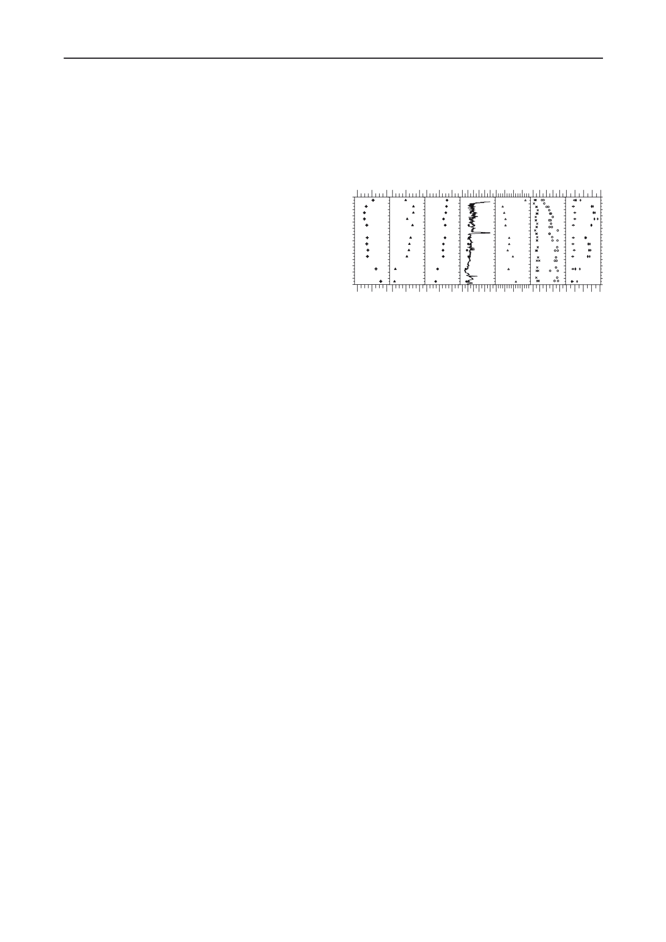
Tan
et al
. (2013) studied another trial embankment
constructed over a 15m thick deposit of very soft clay whose
relevant mechanical properties are shown in Figure 2. Pre-
fabricated vertical drains (PVD) were installed in the soft soil
deposit following a triangular pattern (1.2 m separation). The
trial embankment was 50m long and 14.2m wide, a 50cm thick
sand layer was placed at the bottom of the embankment as well
as a geotextile sheet.
The embankment was instrumented with inclinometers,
displacements markers, extensometers, vibrating wire
piezocones, settlement gauges, stand pipes. Experimental
observations were used to back analyze the embankment using
the Plaxis computer software, using the “soft soil model” for the
clays and the “hardening soil model” for sandy strata. Their
analyses included indirectly the presence of PVDs. To achieve
this, the authors used an equivalent vertical permeability for the
soft clay stratum. The back analysis yielded a value of this
equivalent permeability which turned out to be almost six times
larger than the original permeability of the soft soils.
Figure 2. Mechanical properties of the trial embankment (Tan
et al
.
2013).
Popovic and Stanic (2013) analyze soil-structure interaction
and effectiveness of soil improvement through back-analyses
based on measurements conducted during the early stages of the
construction of a new container terminal in the port of Ploce in
Croatia. The soil profile is formed by a surface layer of silty
sand and low plasticity silt of 8m of thickness followed by a
low to high plasticity clay that reaches 33m of depth. After that,
a low plasticity poorly graded silty sand is founded. Subsoil
treatment consisted in dense and sparse stone columns
(triangular grid 2x2m and square grid 2.8x2.8m, respectively).
Back analyses were performed based data on soil settlement
and pile displacement measured with instruments installed to
monitor the progress of construction. The objective of back
analyses was to establish “actual” soil parameters and the
condition of internal forces and displacements in the structure.
The authors were able to verify the efficiency of planned works
aided by the geotechnical measurements described in the paper.
Finally, the results of numerical models were used as a
means for controlling the construction processes. The authors
point out that it is necessary to perform back analyses during
and after the construction of complex projects in difficult
geotechnical environments on the basis of measurements and
through the collaboration of structural and geotechnical
engineers.
The paper by Massad
et al.
(2013) is based on data from a
work in Santos Harbor, in São Paulo State, Brazil, in which
three experimental fills were built and monitored, one of them
partially with geodrains. The monitoring of earth fills built on
soft clays has been done frequently through the Brazilian
coastline. As the most common measurement is the settlement
along time, the interpretation of the results is usually done by
Asaoka’s Method, generally involving extrapolations that have
given rise to doubts (for instance, about the secondary
consolidation effect) and to a double interpretation, and even to
controversies, especially when it comes to evaluating the
effectiveness of vertical geodrains to accelerate settlements.
The uppermost soil stratum is the SFL clay, a sedimentary
material (fluvial-lagoon-bay) of the Pleistocene that has become
lightly overconsolidated due to erosion, sea level oscillations
and dune action. The authors describe and comment on the
results of extensive soil exploration as well as field and
laboratory testing with which a detailed and thorough
characterization of the SFL clay was possible, for the sites at the
three trial embankments.
In the first experimental site an earth fill was placed in area
reclaimed from the sea. Application of loads was carried out in
three stages and that made it possible to apply Asaoka’s
Method, as shown graphically in the paper. A second
experimental fill (Pilot Embankment 2) was built with a
10 15 20
kN/m
3
14
13
12
11
10
9
8
7
6
5
4
3
2
1
0
Depth (m)
BulkDensity
0.1 0.2 0.3
Compression
Ratio (CR)
0 0.02 0.04
Re-compression
Ratio (RR)
0 2 4 6 8 10
----- Piezocone
Over Consolidation
Ratio (OCR)
0 40 80 120
kPa
Preconsolidation
Pressure (PC)
0 10 20 30 40
kPa
M - Undisturbed
=- Remoulded
UndrainedShear
Strength (Su)
0 40 80 120 160
%
{ -Plastic Limit
Y-Water Content
y -Liquid Limit
Atterberg Limit with
Water Content
CR =Cc / 1+e o RR=C r / 1+e o


