2628
Proceedings of the 18
th
International Conference on Soil Mechanics and Geotechnical Engineering, Paris 2013
horizontal coefficient of consolidation equal to c
h
=7x10
-7
m/s
2
.
The actual consolidation time is expected to be even lower,
considering the actual 2D water flow, the presence of horizontal
layers of higher permeability and the additional discharge from
the secondary pipe drains that are prescribed.
5 SEISMIC GROUND RESPONSE ANALYSES
Besides ground improvement, detailed ground response
analyses were also crucial for the successful completion of the
project. Since, both Profile I & II belong to group type S1 & S2
according to EC8, special study was necessary to define the
proper seismic action and the exact liquefaction potential. Thus,
1D equivalent linear analyses were performed with the
equivalent-linear frequency domain method (e.g. Schnabel et al.
1972). Modulus reduction and hysteretic damping curves were
used as a function of cyclic strain amplitude (Vucetic & Dobry,
1991), and introduced the non-linear behavior of soil layers in
ground response analyses, according to its layers’ plasticity
index. According to EC8 provisions, three different
accelerograms were used, which cover a wide range of
frequencies and are representative of the seismic region.
Shear wave velocities of the improved ground were
computed according to Eq. 5, while the peak ground
acceleration at bedrock outcrop was calibrated to 0.24g,
according to the Greek Annex of EC8 for the area under
investigation. Since no bedrock was found, artificial bedrock
was used at the end of each borehole, while the bedrock shear
wave velocity was assumed to range between 300 and 550m/s,
providing a high impedance ratio compared with the soil
column characteristics. Thus, radiation damping was
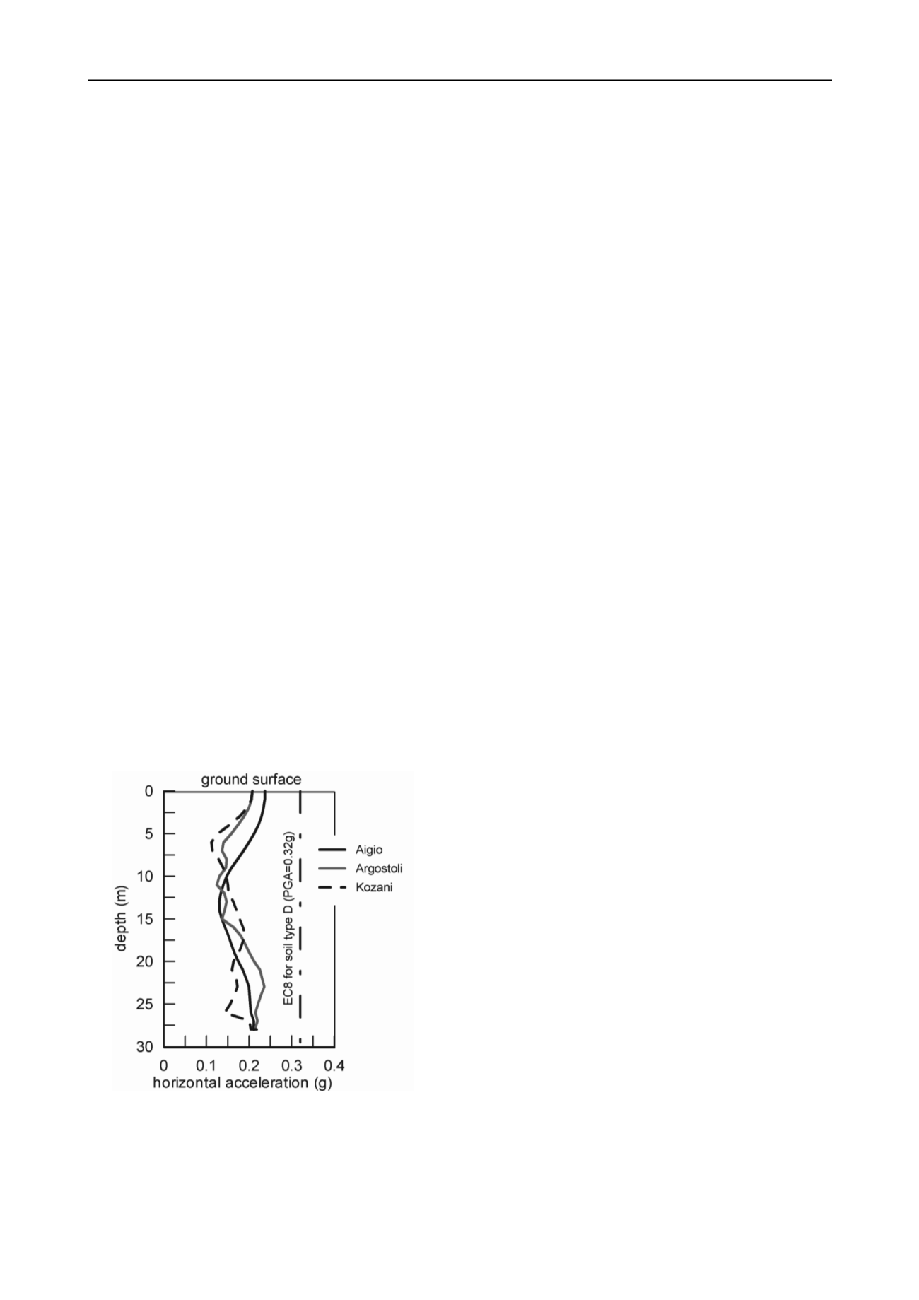
conservatively minimized. Fig. 5 shows representative results
from ground response analyses conducted in Profile II.
Significant de-amplification of the seismic motion is observed,
due to the flexibility of the soil column but also due to the non-
linearity exhibited by the soil layers. The computed peak ground
acceleration at ground surface ranges between 0.20 to 0.24g,
significantly lower from the 0.32g required by EC8 for the
flexible soil type D. Thus, the structural forces due to seismic
loading were significantly reduced, while the factor of safety
against liquefaction was substantially increased.
Figure 5: Distribution of peak ground acceleration with depth for Profile
II using three different accelerograms.
6 CONCLUSION
The present paper presents details of the technical solution
proposed for a road design project in Western Greece, where
major geotechnical issues had to be dealt with for the
foundation of bridges and high embankments. Geotechnical
investigations revealed very poor soil conditions consisting of
silty clays and sands, often with high content of organics, and
high ground water table that locally appeared on the ground
surface. As a result, the foundation of foreseen bridge piers on
surface foundations was excluded and was replaced by a group
of piles with a rigid pile cap. Among a number of possible
methods of soil improvement that were examined, it was finally
decided to proceed with the application of stone columns
followed by preloading. This way, the following were
accomplished:
increase of the general stability of the bridge embankments
increase of the bearing capacity of foundation soil layers
reduction of internal forces of piles
acceleration of the stage of primary consolidation of silty
clay-sands and
reduction of the liquefaction potential of sandy layers.
All of the above effects were verified by site-specific
computations and implemented to the design of the relevant
works
7 ACKNOWLEDGEMENTS
Authors acknowledge the assistance of Harris Lamaris, Civil
Engineer M.Sc. on the geotechnical investigations and the
preliminary liquefaction analyses.
8 REFERENCES (TNR 8)
Baez J.I., Martin G.R.1993., Advances in the design of vibro systems
for the improvement of liquefaction resistance, Symposium on
Ground Improvement. Vancouver
Bouckovalas G., Papadimitriou A., Niarchos D., Tsiapas D. 2011, Sand
fabric evolution effects on drain design for liquefaction mitigation,
Soil Dynamics & Earth. Eng., 31, 1426-1439
Jamiolkowski M., Ladd C., Germaine J.T., Lancellota R. 1985. New
developments in field and laboratory testing of soils.
IX Intern.
Conf. on SMFE
, Vol. 1, 57-154.
Mizuno Y., Suematsu N. & Okuyama K., 1987. Design method of sand
compaction pile for sandy soils containing fines. Journal of
JSSMFE, 53-56
Robertson P.K. 2009. Interpretation of cone penetration tests – a unified
approach. Can. Geotech. J., 46, 1337-1355
Schnabel P.B., Lysmer J. and Seed H.B. 1972. SHAKE: a computer
program for earthquake response analysis of horizontally layered
sites. Report EERC 72-12, Earthquake Engineering Research
Center, Univ. of California, Berkeley
Seed HB, Booker JR. 1977. Stabilization of potentially liquefiable sand
deposits using gravel drains. Journ. of Geotech. Eng., ASCE, 103
(GT7). 757-768
Van Impe W., De Beer E. 1983. Improvement of settlement behavior of
soft layers by means of stone columns. Proc. 8
th
European Conf. of
SMFE, Vol. 1, 309-312
Vucetic M, Dobry R. 1991. Effect of soil plasticity on cyclic response.
Journal of Geotech. Eng. ASCE, 117 (1), 89-107
Weiler W.A. 1988. Small strain shear modulus of clay. Proc. ASCE
Conf. on Earth. Eng. & Soil Dyn. II, New York, 331-335
Youd et al. 2001. Liquefaction resistance of soils: Summary report from
the 1996 NCEER and 1998 NCEER/NSF workshops on evaluation
of liquefaction resistance of soils. Journal of Geotech & Geonv.,
ASCE, 127 (10), 817-833


