2638
Proceedings of the 18
th
International Conference on Soil Mechanics and Geotechnical Engineering, Paris 2013
3.1
Ground improvement
An assessment of a potential of liquefaction during earthquakes
indicated that the loose clayey sand between the depths of 5 to
15 m had a potential of liquefaction during earthquakes with the
peak horizontal ground acceleration of 3.0 m/s
2
. The foundation
level was between depths of 3.6 and 7.2 m, therefore, grid-form
deep cement mixing walls were introduced to cope with the
liquefiable clayey sand below the raft. Figure 2 shows the grid-
form deep cement mixing walls constructed by TOFT method.
The high-modulus soil-cement walls confine loose sand so as
not to cause excessive shear deformation to the loose sand
during earthquakes. The effectiveness of the TOFT method for
the prevention of liquefaction was confirmed during the 1995
Hyogoken-Nambu earthquake (Tokimatsu et al., 1996).
3.2
Design of piled raft
The average contact pressure over the raft is 187 kPa. To
improve bearing capacity of the raft, the grid-form deep cement
mixing walls were extended to the depth of 20 m with the
bottom being embedded in the silty clay with undrained shear
strength of 100 kPa or higher. Furthermore, to reduce the
settlement and the differential settlement to an acceptable level,
180 pre-tensioned spun high-strength concrete (PHC) piles of
0.6 to 1.2 m in diameter were used. The pile toes were
embedded in the very dense sand below the depth of 44 m
enough to ensure the toe resistance as well as the frictional
resistance. The pile was constructed by inserting the precast
piles into a pre-augered borehole filled with mixed-in-place soil
cement. Figure 3 shows a layout of the piles and the grid-form
deep cement mixing walls.
4 INSTRUMENTATION
The locations of the monitoring devices are shown in Figs. 3
and 4. Four piles, P1, P2, P3 and P4, were provided with a
couple of LVDT-type strain gauges at depths of 8.5 m (near pile
head), 20.0 m and 47.0 m (near pile toe) from the ground
Improved soil
columns
φ
1,000mm
800mm
Couple of soil columns lapped and
continuously arranged
Liquefiable layer
Improved soil
columns
Penetration
Withdrawing
Tip treatment
・Discharge of soildified
material
・Stirringandmixing
(a) Grid-form deep cement mixing walls
(b) Construction procedure
Figure 2. Grid-form deep cement mixing method
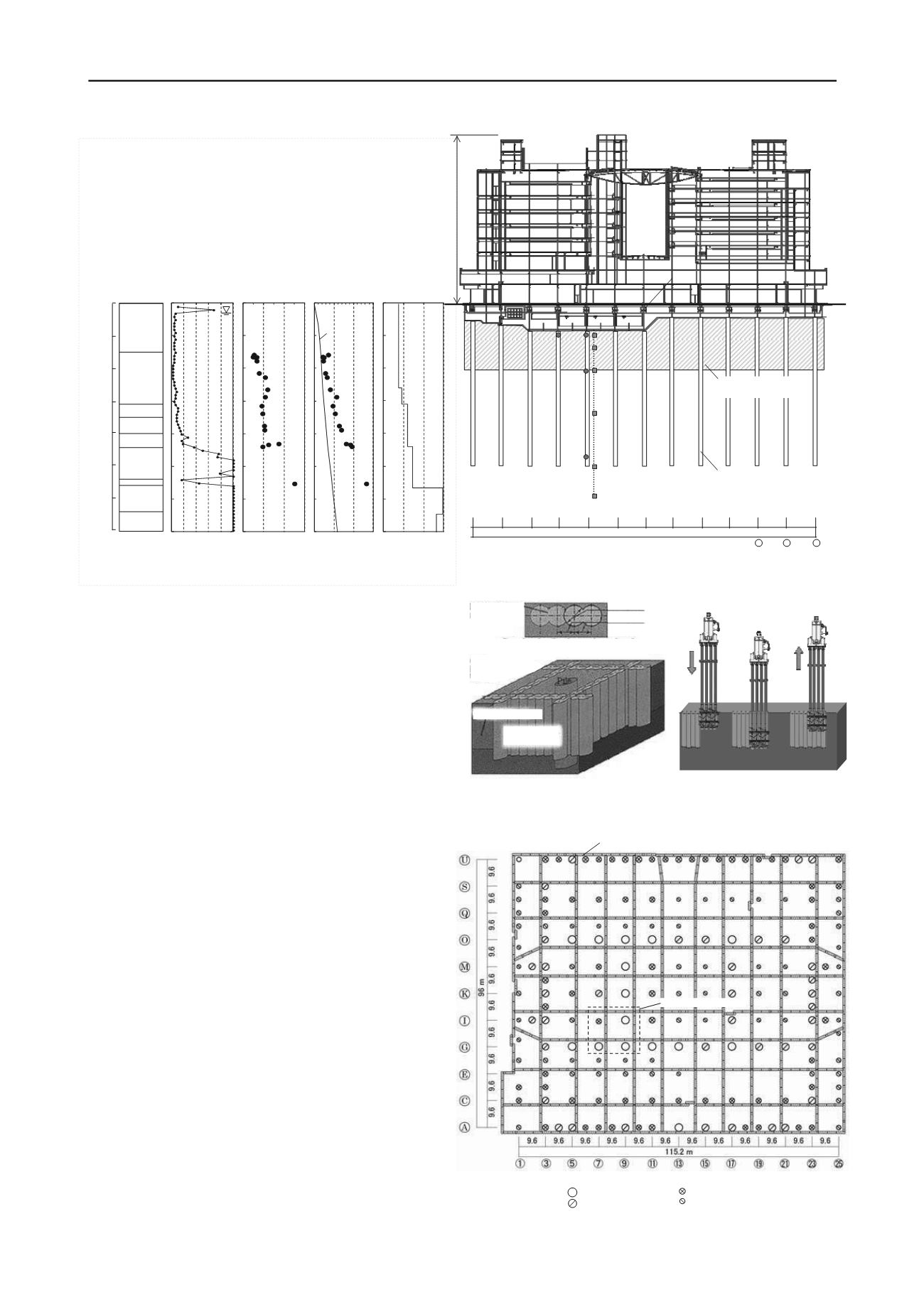
Figure 1. Schematic view of the building and foundation with soil profile
SPT
N-Value
Shear
wave
velocity
Vs
Consolidatio
n
yield stress
Py
Undrained
shear
strength
q
u
/2 (kPa)
0 10 20 30 40 0 100 200 300 0 500 10001500
Effective
overburden
pressure
GL±0
10
20
3
Depth(m
0
40
50
60
70
0 200 400 600
Fill:
Clayey
sand,
Sandy clay,
R bbl
Silty clay
Clayey silt
Silty clay
Clayey silt
Sand
Silt
Sand and
gravel
Sand
55.7m
3.6m
7.2m
20m
49.7m
8.5m
8.5m
60m
50m
35m
20m
47m
14m
20m
PHC pile
Grid-form deep
cement mixing walls
9.6m
9.6m
〃 〃 〃 〃 〃 〃
〃
〃
〃
〃
115.2m
① ③ ⑤ ⑦ ⑨ ⑪ ⑬ ⑮
⑰
⑲
21
23
25
Laminated rubber bearings
Settlement gauges
Grid-form deep cement mixing walls
Tributary area
:φ 1.2m
:φ 1.1m, 1.0m
Pile diameter
:φ 0.9m, 0.8m
:φ 0.7m, 0.6m
Figure 3. Layout of piles and grid-form deep cement mixing walls


