2647
Technical Committee 211 /
Comité technique 211
,
(
b
sc s tot
N R A R A
),
(1)
where N is a required axial force; φ – coefficient equal to 0,92
in this case; R
b
– prism strength of soil cement; A – normal
prism section area of 0,01 m
2
; R
sc
– reinforcement rated
compressing strength equal to 225 mPa ; A
s,tot
– total area of
main reinforcement.
Rated values of abovementioned indices, as well as model
bearing capacity and expected bearing capacity of full-scale
piles are shown in Table 4.
Table 4. Bearing capacity of soil cement prisms and piles by materials
(using the first calculation method)
Series
No.
ρ
f
, %
A
s
,
mm
2
N
,
kN
N
, kN
full-scale pile
1
0.00
0
11.20
179
2
1.13
113
33.70
661
3
2.01
201
51.91
1019
4
3.14
314
75.30
1478
The second method constitutes the method of calculation of
oblique loaded reinforced concrete elements in accordance with
deformation model in the stress-strain state in its supercritical
stage. Axial compression figures its special case. Dynamic pile
formula for definition by material of standard cross-section is
given by
(
)
1 (
2)
b U
U
U b
b U
U
R K
N A AR
K
, (2)
where A, η
U
, K are bearing capacity coefficients.
Table 5 illustrates the bearing capacity of steel soil cement
prisms and expected bearing capacity of soil cement piles.
Table 5. Bearing capacity of soil cement prisms and full-scale piles
(determined by the second method)
Series
Nos.
А
η
u
K
N
u
, kN
N
, kN,
full-scale piles
1
0
1
1.70
11.20
179
2
1.54
1.40
1.70
32.20
635
3
2.73
1.60
1.70
52.41
1033
4
4.27
1.79
1.70
81.68
1616
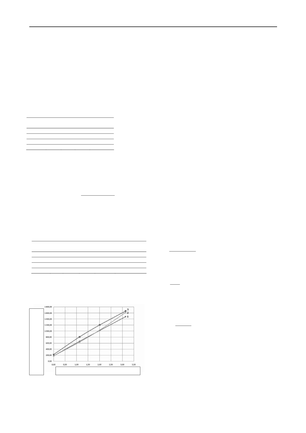
Figure 3 contains relationship: bearing capacity of steel soil
cement samples – ratio of standard cross-section reinforcement.
It also contains relationships determined analytically according
to the aforementioned methods.
Figure 3. Relationship between bearing capacity of soil cement piles by
material N and ratio of standard cross-section reinforcement ρ
f
based on
the following data: 1 – calculation by the first method, 2 – calculation
by the second method, 3 – according to in vitro data.
On basis of the research performed it may be concluded as
follows:
Application of longitudinal reinforcement enables to
considerably increase the soil cement strength;
Comparison of data of analytical calculations of soil cement
strength with in vitro data showed that the described
methods of reinforced concrete structures calculation can be
used for calculation of steel soil cement structures strength;
As for the two above calculation methods the calculation
according to the deformation model shall be given
preference, since it is aimed at calculation of structures at
combined loading. Moreover this method seems to be less
sensitive to soil cement parameter variability.
3 USE OF SOIL CEMENT FOR REGULATION OF
SETTLEMENT SPEED OF BUILDINGS AT
RECTIFYING THEIR ROLL DISPLACEMENT
The method of soil drilling out from bottom of less subsided
foundations for rectifying of roll displacement of buildings is
widely used in Ukraine. For this purpose underworking of the
bottom with help of horizontal drill holes of variable diameters
is usually performed (V. Shokarev, V. Shapoval, 2009).
Technological parameters calculation for underworking of
soil under foundation (diameter and pitch of drill holes) is
carried out by formula
,
S d t
(3)
where S is the required settlement for rectifying of roll
displacement of a building; d – drill hole diameter; t – pitch of a
drill hole.
Possessing the research findings related to changing of zero-
air dry unit weight (
d) under bottom of foundation and
experimental data on critical density of soil (ρsr.) – vertical
pressure relationship we can determine the soil layer depth,
where drilling of horizontal drill holes and soil structure
destruction will be carried out
.
1 /
d кр
S
h
(4)
Time of conditional stabilization of building’s settlement
shall be determined by formula
,
tg T
V
(5)
where V is the value of conditional stabilization equal to 0.143
cm per day.
Influence coefficient tgρ shall be determined by quotation
Rated bearing capacity of soil cement piles by
material, N, kN
1
1
,
/
S S
tg
nt t
(6)
where S, S
1
means the value of building’s settlement received
according monitoring data; t, t
1
means time interval between
monitoring stages.
If stabilization of building’s settlement during rectifying of
its roll displacement takes place prior to fulfillment of required
settlement, additional breaking up of soil under foundation
bottom shall be necessary. In order to forecast the time of
stabilization of building’s settlement after fulfillment of
required settlement the soil cement mortar using drilling mixing
technology shall be fed to the foundation bottom. It allows to
reduce the building’s settlement speed and to achieve the
required value.
Ratio of standard cross-section reinforcement ρ
f
, % %
i f


