2631
Technical Committee 211 /
Comité technique 211
therefore adopted, using a method developed and extended from
EBGEO, which at the time of planning was only available in its
2004 draft stage. This extended design method was verified for
similar subsoil and loading conditions (Vollmert et al., 2006). The
anticipated further settlements at the level of the reinforcement
were estimated at less than 50 mm after termination of
construction.
Comparisons with the current EBGEO (2010), available in its
final form now that construction is complete, show that the design
and verification of the system is sufficiently robust to cater even
for the special case "Loss of Subgrade Reaction" in Load Case 3.
It must however be noted, that extreme changes in subgrade-
reaction conditions – such as its total loss – will result in load
redistribution in the sub-base layer. The long-term influence of
these on the serviceability can currently not be finally estimated
and is the subject of research. Taking serviceability aspects into
account, a conservative, realistic estimate of foundation conditions
is therefore critical in the design of such subsoil-improvement
projects.
2.3.4 Accompanying measurement
The selection of the subgrade-reaction value at the underside of
the reinforced layer is therefore a critical starting parameter for
design. Values for this are usually derived from the stiffness
modulus of the subgrade and the thickness of the weak soil layers.
The actual reaction is, however, a variable whose value depends
on, among other things, the soil improvement during the
construction phase, consolidation processes, the stiffness of the
geogrid-reinforced foundation layer and the sub-base layer.
In order to obtain further information on the subgrade reaction
and the actual behaviour of the structure, it is necessary to
investigate such structures in-situ. During the development of
Hongkongstrasse, boundary conditions for monitoring with a
measurement system were ideal, as not only the foundation soil
conditions, but also the geometric conditions and the alterations
anticipated in the medium term (development of the investor areas
and resulting encroachments into the stress distribution in the
structure) were seen as exemplary for the particular situation of
HafenCity Hamburg.
The objective of the measurement programme is therefore the
investigation and measurement of
-
the state of stress in the geogrid
-
the development of soil arching, taking construction and
operational conditions into account
-
the proportions of the load allocated to the supports and
the weak layer
-
the influence of variations in water-table level in the
foundation soil, and
-
the deformation situation at foundation level.
3. CONSTRUCTION AND MEASUREMENTS RESULTS
3.1 Sand pre-loading layer and vertical drains
After the necessary clearing away of foundations, the removal of
old services and the search for unexploded ordinance, in the
southern part of Hongkongstrasse, vertical drains were hydrau-
lically driven into the foundation soil. Plastic strip drains with a
width b of around 100 mm were used.
In installing the strip drains it was required to ensure that a
depth of soft soil of around d = 1.0 m remained under the drains as
a natural barrier to the lower groundwater aquifer (lower sands).
After this, the sand layer (including any pre-load) was placed.
Sand with a silt content ≤ 5 % by weight, a uniformity coefficient
U of approx. 2 and a rating of Z0 in accordance with the LAGA
guidelines was to be used. The sands were compacted in layers to
at least medium compaction density.
Below the level at which the sand was laid, settlement-
measuring rods, each adjustable in length and with a base plate
(1 m x 1 m) were installed, and these were continuously monitored
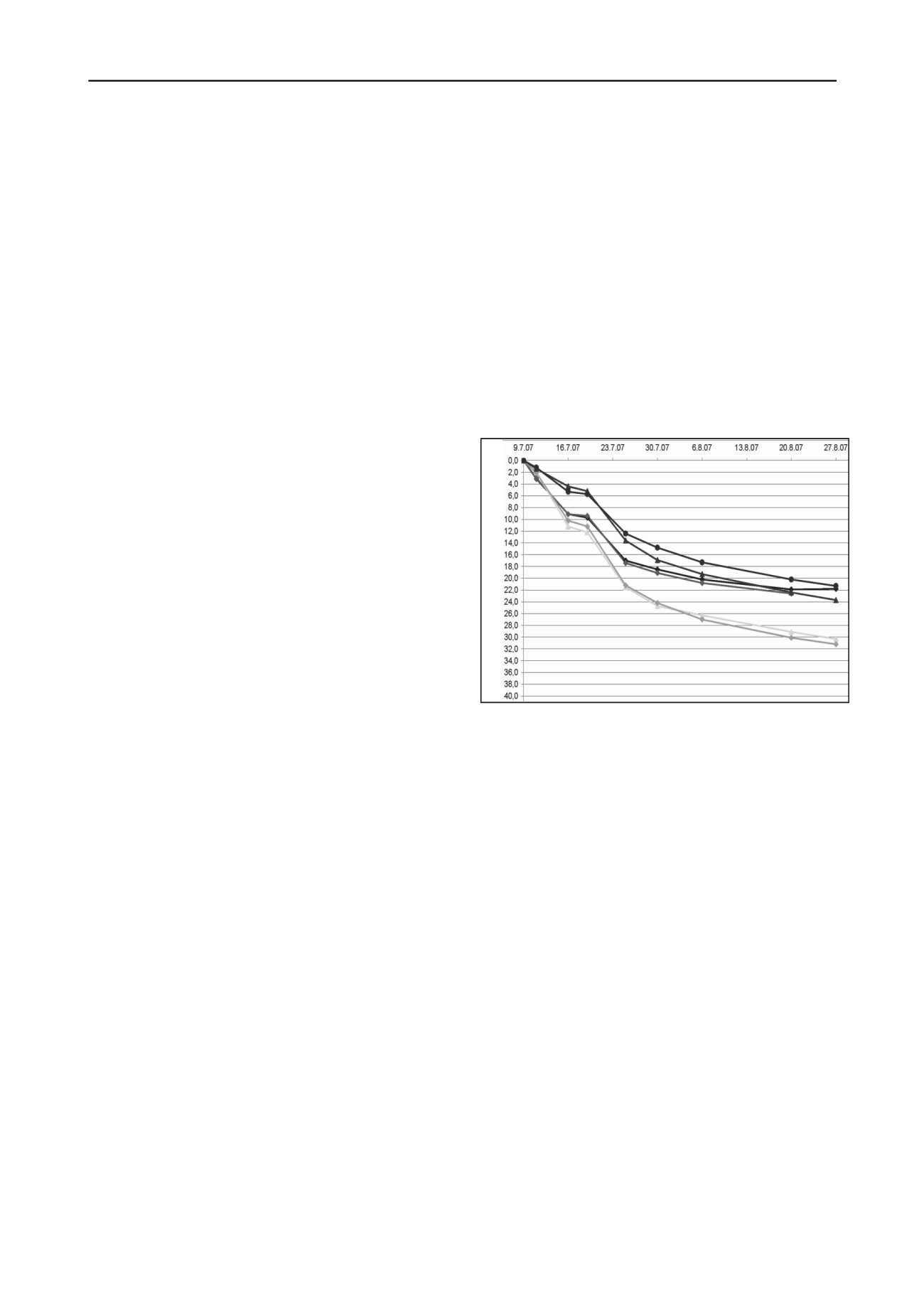
while the pre-load was in place. A plot of settlement against time
is shown in Figure 4.
3.2 Use of lightweight aggregate (expanded clay)
Lightweight aggregate in the form of expanded clay was used in
the northern area of Hongkongstrasse.
Various active services crossed the construction area and it had
to be ensured that these were not damaged during the excavation
of trenches, around 3.5 m deep. In the area of the services, the
expanded clay was installed in so-called big bags as a foundation
for the services. In the remaining areas, the expanded clay was
placed, spread, and compacted in layers to the design height (base
of sand protection layer) (Figure 5).
Settlements [cm]
Figure 4: Development of settlement during loading phase
3
.3
Piled, geogrid-reinforced sand base layer
3.2.1 Construction
For the required design working load of 500 kN, partial-
displacement bored columns with a diameter of 420 mm and an
unreinforced, fresh-in-fresh tapered cast cap C25/30 with a cap
diameter of 600 mm were installed by GKT Spezialtiefbau GmbH
working for Eggers Umwelttechnik GmbH.
High-strength, high-modulus geogrids Secugrid 200/40 R6 and
Secugrid 400/40 R6 were used to reinforce the sand base-layer.
The construction of the geogrid-reinforced sand layer had to be
carried out with overlap. A length of grid from the lower layer,
which was laid across the width of the base layer, was rolled and
stored at the edge of the fill. After the lengthwise reinforcement
and the fill had been placed, the stored roll was pulled up,
wrapped round the fill, and overlapped by the length required in
the design calculations (Figure 6). For a workmanlike placing it is
therefore necessary to ensure that the roll overlaps are arranged in
a staggered pattern in order to avoid distortion and twisting of the
geogrids.
The results of the measurements have been published by
Weihrauch et al. (2010) indicating the expected performance as
well as meeting the deformation requirements as given by the
design.


