2627
Technical Committee 211 /
Comité technique 211
of the bridge embankments) is considered substantial, while its
secondary effects such as the acceleration of consolidation at
layers that were found under-consolidated and the reduction of
downdrag forces at piles (i.e. by allowing the consolidating soil
to settle before construction) increase its efficiency. The
prescribed pre-loading embankment were wider from the bridge
embankment / pile cap by 2.5-3.0m at each side, in order to
apply uniform stress at the area of interest, while its height
generally varies between 3 and 7m.
Stage construction of pre-loading embankment was decided
(with height increments between 1.5-2.0m), due to the poor soil
conditions, followed by continuous settlement and pore-
pressure dissipation recordings. Figure 2 presents the
anticipated final (after improvement) distribution of S
u
with
depth for the CPT recording presented in Section 3.
Gravel pile installment is prescribed ahead of pre-loading,
consisting of 0.80m diameter piles in a 1.80 x 1.80m square
arrangement (denoting replacement percentage equal to a
s
=
0.78x (0.8/1.8)
2
=15.4%). Gravel pile length varies between 8
and 13m, depending on soil conditions.
The installation of gravel piles increased the mechanical
properties of the upper cohesive fine-grained layers and
subsequently increased the general stability of bridge & pre-
loading embankments. The following equivalent strength
parameters were used (Van Impe & De Beer, 1983):
c
eq
= (1-a
s
) S
u,f
(4a)
tanφ
eq
= [na
s
/(na
s
+1 –a
s
)]tanφ
1
(4b)
where
c
eq
& φ
eq
denote the equivalent cohesion & friction angle
of the composite system respectively,
φ
1
denotes the friction
angle of gravels (assumed equal to 42
o
),
a
s
denotes the
replacement ratio (equal to 0.154) and
n
denotes the ratio of the
load taken by the gravel pile versus the surcharge load. The
contribution of geostatic stresses is omitted; while outside the
embankment limits (where no surcharge is applied)
n
equals
1.0. The improved shear strength of the composite system,
combined with the increase of the undrained shear strength due
to pre-loading proved adequate for the construction of the
bridge embankments with acceptable factor of safety under both
static and seismic conditions (e.g. the static F.S. increased from
0.64 to 1.51 for a representative height of 4m).
Note that, besides the improvement of shear strength
characteristics, the inclusion of gravel columns combined with
pre-loading has altered the seismic ground response relative to
free-field. In order to take into account this effect, the shear
wave velocity and the spring stiffness in P-y curves of the
relevant soil layers were appropriately increased. Namely, the
formula presented by Baez & Martin (1993) was used for the
estimation of the maximum shear modulus of the composite
system:
G
max,eq
= G
max,i
a
s
+ G
max,p
(1-a
s
)
(5)
where
G
max,eq
is the maximum equivalent shear modulus,
G
max,i
is the maximum shear modulus of the fine-grained layer after
pre-loading,
G
max,p
is the maximum shear modulus of the gravel
pile and
a
s
is the replacement ratio (here 0.154). The maximum
shear modulus of the fine-grained layer after pre-loading was
computed as follows (Weiler, 1988):
G
max,i
= G
max,o
OCR
0.5
(6)
where G
max,o
is the maximum shear modulus of unimproved
soil, as computed by Eq. 2. The maximum shear modulus of the
gravel pile was computed assuming a dense configuration
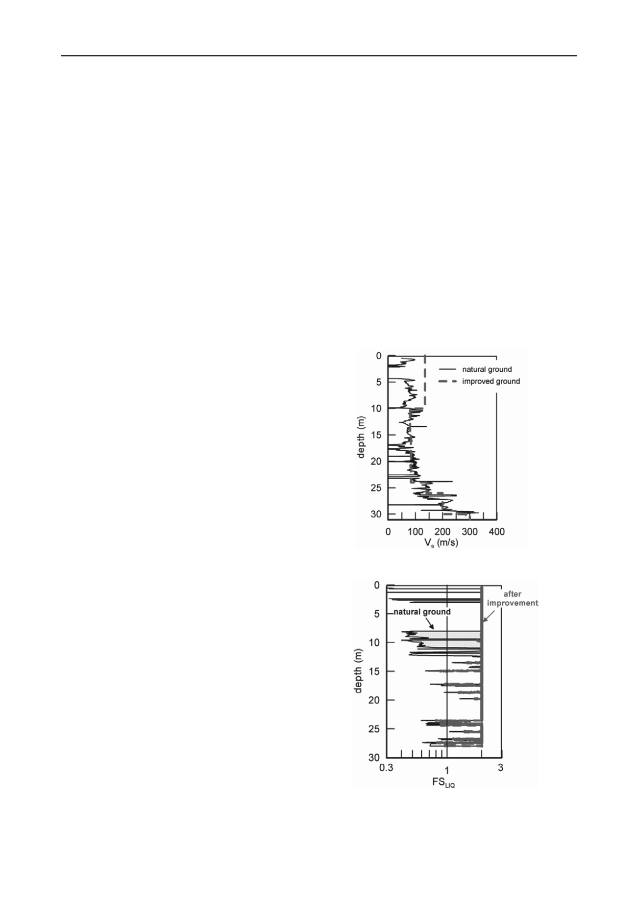
(e=0.55). Figure 3 presents the shear wave velocity profile of
the composite system for the CPT recording of Fig. 1. The
average shear wave velocity V
s,30
for this profile increased from
86 to 140m/s, reflecting stiffer ground conditions. This increase
was also implemented to the P-y curves, by increasing the
horizontal subgrade reaction coefficient k. The increase was
assumed proportional to the ratio G
max,eq
/G
max,o
, while for the
unimproved soil coefficient k was computed according to
DIN4014 for bored cast-in-place piles.
For the case of Profile II, where a non-cohesive liquefiable
layer is present, the gravel piles are expected to act as a
countermeasure against liquefaction. The gravel piles will be
constructed via bottom-feed vibro-replacement, while a proper
gradation curve range is prescribed in order to ensure the
effective drainage of earthquake-induced excess pore-pressures.
During vibro-replacement, the non-cohesive layer is expected to
be densified and increase its resistance to liquefaction. Based on
Mizuno et al. (1987), the average measured tip resistance is
expected to increase between gravel piles from 4.5MPa to
9.5MPa, providing an adequate liquefaction resistance. Figure 4
compares results from the preliminary (before improvement)
and the detailed (after ground improvement) liquefaction study,
which show the minimization of liquefaction potential. The
densification of the non-cohesive layer due to pre-loading and
the potential dissipation of excess pore pressures were
conservatively ignored. It is noted that even if densification was
ignored, drainage through gravel piles would retain excess pore
pressure ratio r
u
well below 0.5, as computed according to Seed
& Booker (1977) and Bouckovalas et al. (2011) for the given
characteristics and gravel pile geometry.
Figure 3: Distribution of shear wave velocity with depth for profile I,
before and after the improvement
Figure 4: Factor of safety against liquefaction for Profile II, before
(preliminary results) and after improvement (detailed study).
Finally, consolidation process is expected to be accelerated with
the presence of gravel piles. Excess pore pressures for each
loading stage are expected to diminish within 19 days, assuming
conservatively only radial flow towards the gravel piles and


