2626
Proceedings of the 18
th
International Conference on Soil Mechanics and Geotechnical Engineering, Paris 2013
geotechnical conditions at these areas can be simplified in two
main profiles.
Soil profile I (Fig. 1) is encountered in the majority of the
bridge sites. Its main characteristic is the surficial layer of fine-
grained medium plasticity soil. According to the geotechnical
exploration results, this soil layer consists mainly of low to
medium plasticity silts (ML) and clays (CL), with thin layers of
high plasticity silts (MH), fat clays (CH) and organic clays
(OL). The thickness of this layer varies between about 22.5 to
35m. Below this layer, to the depth of 40m, either a medium to
dense non-cohesive soil unit (SC, SM) or a dense cohesive soil
unit (CL) are present. Rock or any other rock-like geological
formation was not encountered at any of the locations explored.
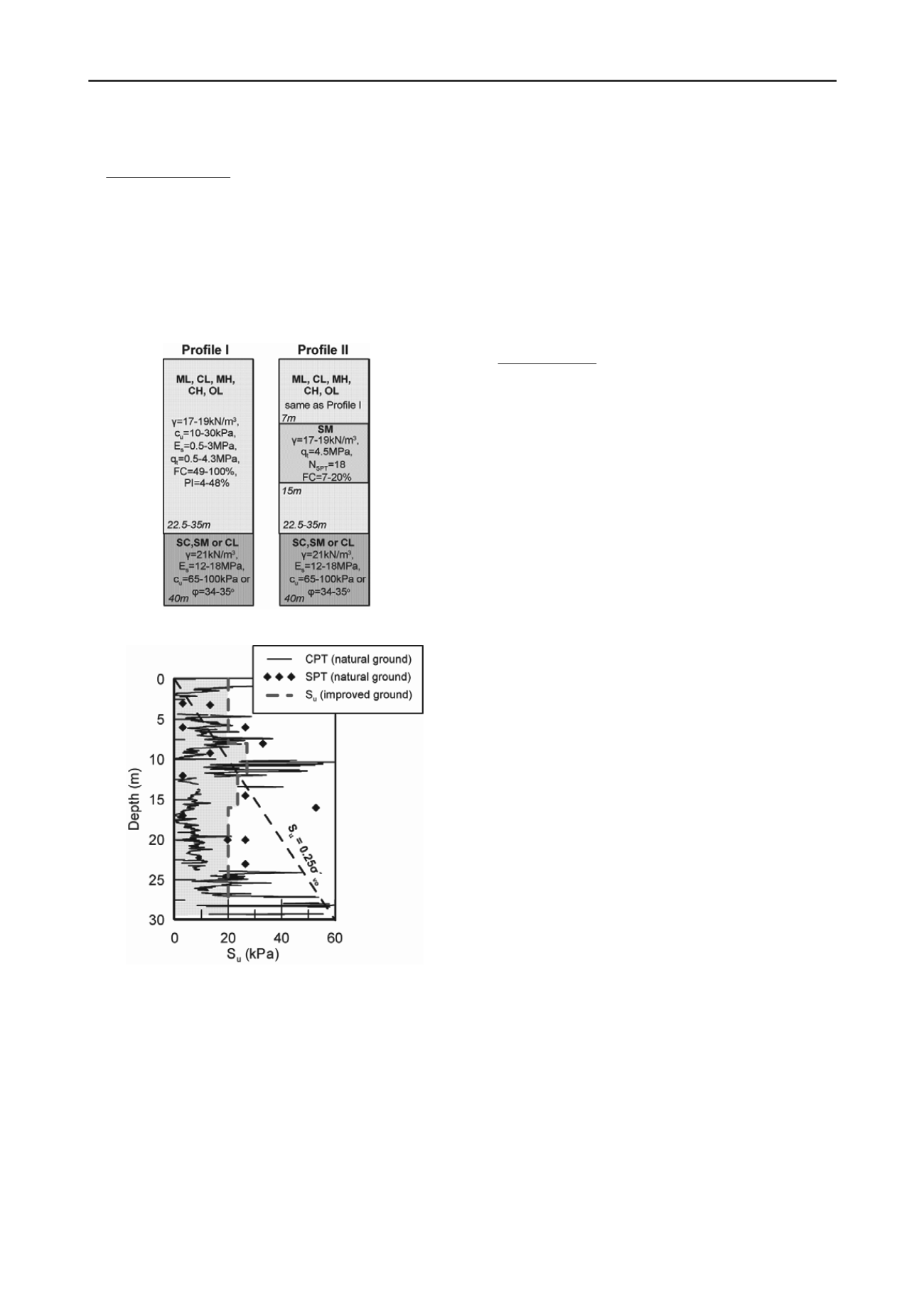
Figure 1: Representative geotechnical profiles
Figure 2: Distribution of undrained shear strength with depth for profile
I conditions, before and after the improvement
Figure 2 presents an estimation of the undrained shear
strength of the surficial fine-grained soil unit of Profile I, based
on the results of typical CPT & SPT recordings. An estimation
of undrained shear strength for normally consolidated clays is
also presented, based on Jamiolkowski et al. (1985) (see Eq.1):
S
u
= 0.25 σ΄
vo
(1)
where σ΄
vo
is the geostatic effective vertical stress. Comparing
these two estimations, it is concluded that the surficial fine-
grained layer is normally or even at some depths under-
consolidated, with low values of undrained shear strength. Thus,
the bearing capacity of this formation is considered low and
significant settlements are expected during loading, with the
necessary consolidation time to exceed the acceptable time
limits (horizontal coefficient of consolidation ranging between
c
h
=7x10
-7
– 9x10
-6
m
2
/sec based on CPTu dissipation tests). The
lateral resistance of this layer is also considered very low,
leading to large horizontal displacements and structural forces,
especially during seismic loading.
With regard to the seismic response, profile I belongs to
group type S1 according to EC8. The average shear wave
velocity V
s,30
generally ranges between 85 and 140m/sec, as
computed from the CPT recordings:
G
max,o
= (q
t
– σ
v
)x0.0188x10
0.55Ic+1.68
(2)
where I
c
is a soil behavior type index (Robertson, 2009). Thus,
special study is required for the definition of the seismic action,
which will take into account the non-linear response of the soil
layers and the dependence of soil moduli and internal damping
on cyclic strain amplitude.
Profile II (Fig. 1) represents the soil conditions prevailing at
one bridge site. The soil conditions resemble those of Profile I,
with the exception of an 8m thick layer of loose silty sand that
interrupts the surficial fine-grained formation. This non-
cohesive formation (SM according to USCS) is relatively close
to ground surface (at the depth of 7m), while it is classified as
non-plastic, with fines content between 7 and 20% and
potentially liquefiable under seismic conditions.
A preliminary liquefaction analysis with NCEER
methodology (Youd et al. 2001) for CPT recordings revealed
that this non-cohesive formation is liquefiable. As shown in Fig.
4, the factor of safety against liquefaction is well below unity
for the silty sand layer, revealing its high liquefaction potential.
Hence, although this soil layer presents higher stiffness
(V
s,30
=140m/s) and bearing capacity for static loading, as
compared to the clay layer, its liquefaction potential deteriorates
its mechanical properties. Thus, during earthquake loading, loss
of bearing capacity, lateral stiffness degradation and settlements
are expected to occur, increasing this way superstructure
displacements and structural forces. Furthermore, Profile II is
now characterized as Group type S2 according to EC8 and
special study is needed to define the seismic action and the
exact liquefaction potential.
4 DESIGN CONCEPT
As a result of the existing poor soil conditions, the foundation
of the foreseen bridge piers on surface foundations was
excluded and was replaced by a group of piles with a rigid pile
cap. However, due to the high seismicity of the area, the very
low P-y reaction of the soft silty clays and the eventual
liquefaction of the silty sand layer led to extreme internal forces
of the piles and increased dis-proportionally the cost of the
project. Hence, the necessity of an acceptable solution in terms
of both dimensions and cost, led to the decision to improve the
top part of the natural soil.
Among a number of possible methods of soil improvement
that were examined, it was decided to proceed with the
application of gravel piles followed by preloading. Plastic
drains are also prescribed to act as secondary drainage system
for greater soil depths.
The main aim of pre-loading was to increase the undrained
shear strength of the surficial fine-grained soil unit. The
improved undrained shear strength (when the increase of
effective stress due to surcharge exceeded 10% of its initial
value), was estimated according to Eq. 4:
S
u,f
= S
u,o
OCR
0.8
(3)
with S
u,o
reflecting the anticipated undrained shear strength for
normally consolidated clays (see Eq. 2). The increase of
effective vertical stress at each depth was computed according
to the well known Westergaard solutions, taking into account
the increase of soil stiffness at upper layers, where gravel pile
installation accompanies pre-loading. The effect of pre-loading
reduces with depth, while a percentage of the surcharge load is
used for the increase of OCR, due to the distribution of the
external load between gravel piles and original soil. Despite
that, the anticipated increase of undrained shear strength at
upper layers (i.e. at layers that are crucial for the overall safety


