2630
Proceedings of the 18
th
International Conference on Soil Mechanics and Geotechnical Engineering, Paris 2013
loading layer and vertical drains to pre-empt settlements is an
economical standard method.
To accelerate consolidation, vertical drains are installed in the
area to be loaded. The planned, elevated cross-section is then
constructed, and an additional 2.0 to 3.0 m thick sand pre-load is
placed.
The consolidation of the weak organic layers is monitored over
time using settlement gauges.
After the time required for settlement (usually at least three
months), during which no further construction takes place, the
sand pre-load is removed to the agreed planned height and the
structure passes out of the responsibility of the earthworks
contractor.
2.2 Use of lightweight aggregates (expanded clay)
In areas where pre-emption of settlement is impractical because of
local structures or services, lightweight aggregates are often used.
These materials significantly reduce settlements resulting from the
raising of ground levels.
For forecast residual settlements of around 50 to 70 mm, the
lightweight materials are placed to a depth of around MSL + 2 m.
The expanded-clay layer is wrapped in a nonwoven geotextile
to prevent particle displacement and leaching-in of soil.
The use of expanded clay is regulated in the "Merkblatt über
die Verwendung von Blähton als Leichtbaustoff im Untergrund
von Straßen" of the Forschungsgesellschaft für Straßen- und
Verkehrswesen (FGSV).
2.3 Construction of a piled, geogrid-reinforced sand layer
2.3.1 Construction method and system chosen
The system is characterised by vertical columns (lime-cement
treated gravel, unreinforced) and an overlying sand layer
horizontally reinforced with geogrids. Use is made of the arching
effect of the overburden sandy soil while the foundation soil acts
as a bedding layer. In contrast to concrete slabs on (reinforced
concrete-) piles, in which the individual elements are very stiff in
comparison to the surrounding soils, there is a pronounced
interaction between the columns, geogrid and the foundation soil
in the system described here.
In contrast to
the methods described under 2.1 and 2.2, the
foundation soil in this system is only subjected to low additional
stresses. The major part of the vertical stresses is transferred in a
concentrated manner by the vertical columns into the firm
foundation soil. The system settlements remain proportionally
very small both during and after the construction phase.
When correctly designed, the system possesses significant
reserves of bearing capacity, so that subsequent interventions and
changes within limits in the foundation soil have no influence on
the serviceability of the structure.
The placement grid of the supporting elements should be
designed to transfer the geogrid loads in an orthogonal manner.
For Hongkongstrasse, this resulted in a rectangular grid with a
spacing of 2.3 m normal to the embankment axis and 2.5 m in the
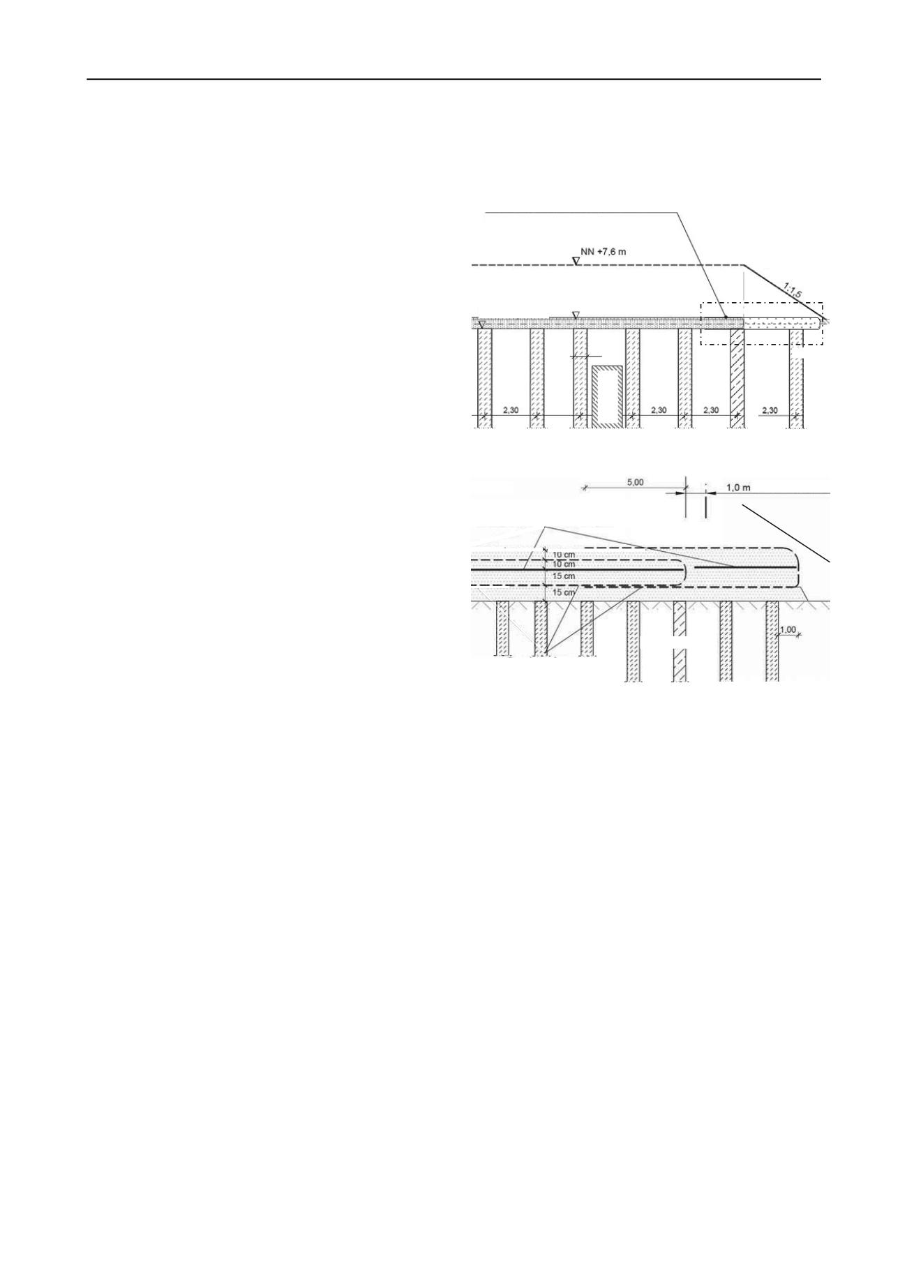
axial direction; the diameter of the elements was 0.6 m (Figure 2).
Reinforced-concrete columns with continuous steel reinforcement
were used at the edge of the structure to cope with a bending
moment (e.g. should any excavation be required at a later date) as
a result of lateral pressure.
The geogrid-reinforcement is installed 150 mm above the
columns in order to guarantee adequate safety against shear during
the construction phase, and in case of large settlements. The
reinforcement is placed at right angles to the placement grid, so
that the layers are cross-laid in the longitudinal and transverse
directions of the embankment.
In the transverse direction, the constructive situation leaves
practically no room to anchor the geogrid. The design requirement
of a short-term tensile strength of 400 kN/m is therefore assigned
to two layers, which are wrapped round at the edges of the
structure, and overlapped in the upper layer.
MSL +5.2 m (prev. GL)
MSL +4.8 m
0.6
reinforced-concrete
l
filled
old sewer
Detail A
0.5 m geogrid – reinforced sand layer
Figure 2: Cross section – piled sand layer
Figure 3: Detail A – sketch of system showing reinforcement placing
(vertical scale greater than horizontal)
2.3.2 Points of constructive relevance near Hongkongstrasse
To avoid the risk of subsequent construction activity of investors
endangering or destroying sections which have already been built,
an area of 1.0 m of the traffic section must be able to be removed.
Fill which intrudes into investor areas must also be removable.
In order to prevent any damage to the embankment-support
system, the geogrid-reinforced fill layer was built with sufficient
overlap (Figure 3). The outer section can thus be removed in the
course of normal earthworks.
2.3.3 Design and verifications
The design of the support system is performed for the columns
and the geogrid-reinforced fill layer in co-ordination with one
another.
The columns are designed for the total load, and the
contribution of the subsoil to load bearing and subgrade reaction
between the columns is neglected.
The geogrid-reinforced layer was designed according to a
verification concept which has already been used and proven itself
several times in HafenCity Hamburg. The limit bearing capacity
was first verified in accordance with a suggestion from Kempfert
et al. (1997). A conservative value for subgrade reaction was used.
This verification procedure does not enable any deformations to
be inferred.
However, verification of serviceability and of deformation
limitation is compulsory for all construction projects in the
HafenCity Hamburg. A complementary design procedure was
1:1.5
(for investors)
reinforcement in longitudinal direction,
Secugrid 400/40 R6
weak layers
reinforcement in cross‐direction,
Secugrid 200/40 R6


