2548
Proceedings of the 18
th
International Conference on Soil Mechanics and Geotechnical Engineering, Paris 2013
0
50
100
150
200
250
0
50
100
150
200
250
300
350
盛 土
盛 土
Floating
All columns reached
bearing layer
盛 土
Walls reached
bearing layer
Limit value
Optimum arrangement
Confined range
□ ○
Result for Saga (Example)
■ ●
Result for Kumamoto
(
○ ・●
: Optimum arrangement
)
Improvement volume per one meter in a longitudinal direction (m
3
/m)
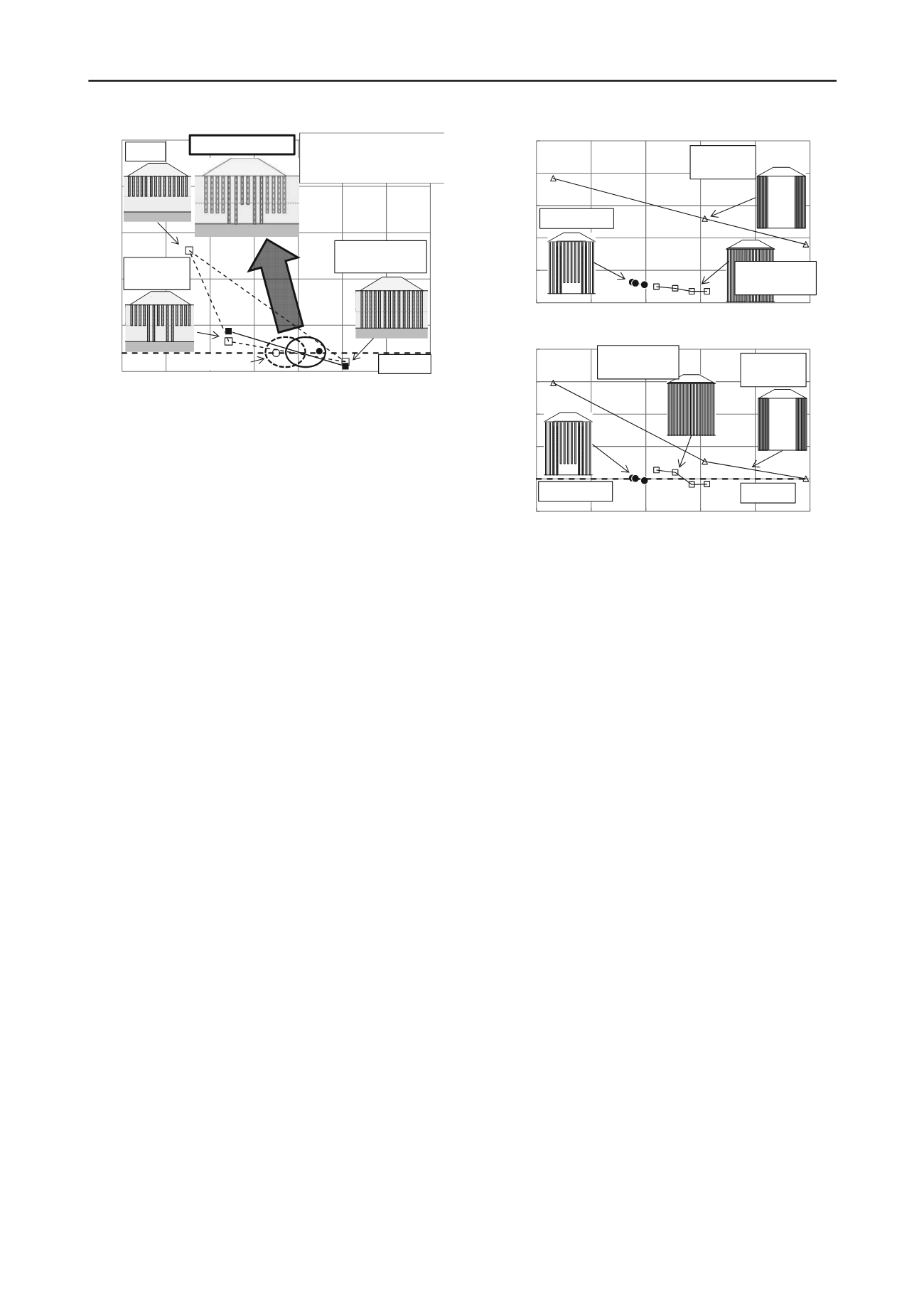
Figure 9.Example of confining the range of consideration and the result
of the consideration for in-situ construction in Kumamoto
in which γ is the unit weight of the embankment, H is the height
of the embankment and
q
uck
is the design strength of the deep
mixing columns.
2) Confine the range of consideration: For the planar
arrangement noted above, the deformation of three
arrangements with different improvement depths(as shown in
Fig.9) is calculated. The relation between the improvement
volume and the deformation of the three arrangements is
illustrated in Fig. 9. The range of consideration is narrowed by
comparing with the limit value of deformation in the adjacent
area.
3) Identify the optimum arrangement: The optimum
arrangement in the range noted above is the arrangement with
the lowest improvement volume that satisfies the limit value.
Figure 9 shows the results of a search for the optimum
arrangement in areas along the Ariake Sea in Saga Prefecture.
Figure 9 also showsthe results of a search in Kumamoto as an
example of an arbitrary parametric study. The positional relation
between both cases is fitted and the results indicate the
effectiveness of the search method.
5 COMPARISON WITH CONVENTIONAL METHODS
To confirm the effect of displacement suppression, a hybrid
arrangement is compared with conventional columns
arrangements as well asan arrangement in which the columns
are equidistant and narrowly spaced.
Under the same geological conditions and embankment
height as in the Kumamoto case, the settlement of the
embankment and at a point 10 m from the embankment toes of
each arrangement were calculated using two-dimensional
analysis.
Figure 10 shows the relation between individual settlement
values and improvement volumes per meter in the longitudinal
direction. Regarding settlement of the embankment, the
settlement of the hybrid arrangement and the equidistant
arrangement are lower than the arrangement under the slopes,
confirming the effect of displacement suppression. For the
settlement ata point 10m from the embankment toes, the hybrid
arrangement is the lowest among same improvement volumes.
When the limit value of settlement in the adjacent area is 20mm,
the hybrid arrangement is more effective than conventional
methods in reducing the improvement volume.
6 CONCLUSIONS
On-site measurements confirmed the method’s effectiveness in
suppressing displacement. The validity of deformational
estimation using two-dimensional effective stress analysis also
0
200
400
600
800
1000
0
100
200
300
400
500
Settlement of embankment (mm)
New technique
Equally arrenged
in low ratio
Arrangement
under slopes
(a)
Improvement volume per one meter in a longitudinal direction (m
3
/m)
0
20
40
60
80
100
0
100
200
300
400
500
Settlement of a point 10m away
from embankment toes (mm)
Limit value
Equally arrenged
in low ratio
Arrangement
under slopes
New technique
(b)
Improvement volume per one meter in a longitudinal direction (m
3
/m)
Figure 10.(a) Settlement of embankment (b) Settlement at a point 10
meters from the embankment toes.
was confirmed. However, little difference was seen in the
estimation of stress and strain distribution in the walls.Using
individual material properties for the walls, however, is
effective.The two examples of searching for the optimum
arrangement using the method proposed in this paper confirmed
the method’s effectiveness. Analytical comparison ofthe new
method with conventional methods also confirmed the
economic efficiency of the new method.
7 ACKNOWLEDGEMENTS
The development of this column link method is the result of
collaborative research involvingthe Public Works Research
Institute, Japan, and thirteen private corporations in Japan. The
authors are particularly gratefulfor the kind assistance of
ShouichiTsutsumi (PWRI), Hirotaka Kawasaki (Shimizu Corp.),
ShouichiTsukuni (Takenaka Civil Eng. & Const. Co., Ltd.), and
NaotoshiShinkawa (Fudo Corp.).
8 REFERENCES
Miki, H. and Nozu, M. 2004. Design and numerical analysis of road
embankment with low improvement ratio Deep Mixing
method,
Geotechnical Engineering for Transportation Projects
, Vol.
2,1935-1402.
Ishikura, R. Ochiai, H. and Matsui, H. 2009. Estimation of settlement of
in-situ improved ground using shallow stabilization and floating-
type columns,
Proceedings of 17
th
International Conference on Soil
Mechanics and Geotechnical Engineering
, 2394-2398.
Miki, H. Okochi, Y. and Makino, M. 2011. Evaluation of constraint
effect of DMM with varied shape and arrangement of stabilized
bodies using centrifuge model test,
Proceedings of Indian
Geotechnical Conference
, 501-504.
Tsutsumi, S. Sawamatsu, T. Iso, Y. and Oshita, T. 2009. Centrifuge
model experiment of new improvement type in deep mixing method
with steel tied by cable for lateral flow,
Deep mixing 2009 Okinawa
symposium
.
Sekiguchi, H. and Ohta, H. 1977. Induced anisotropy and time
dependency in clays, Constitutive equations of soils,
Proceedings of,
9
th
International Conference on Soil Mechanics and Foundation
Engineering
, 229-238.


