2538
Proceedings of the 18
th
International Conference on Soil Mechanics and Geotechnical Engineering, Paris 2013
The modified geotextile tube (M-GT) introduced in this
paper is an innovative application, which combines the structure
/ shape of a “geotextile tube” and the method of installation of a
“geotextile container”. The diameter of M-GT is 5m and the
length is 25m (limited by barge length). The theoretical
maximum volume of M-GT is 490m3. However, for practical
reasons, the filled volume is only about 290m3 or 60% filled in
this project.
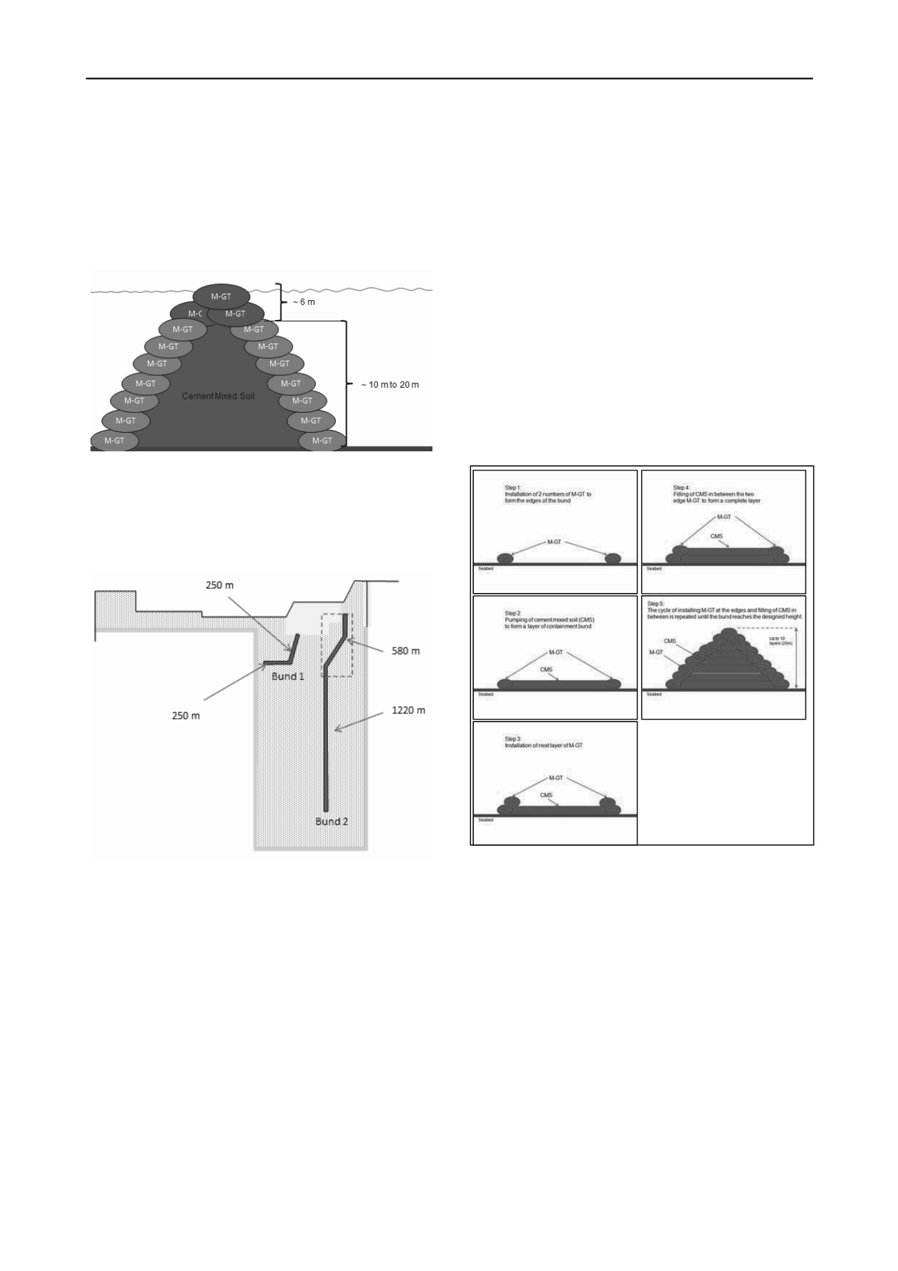
Figure 2 Typical cross section of geotextile containment bund
Two geotextile containment bunds were constructed in this
project. The length of bund 1 is 500 m and bund 2 is 1800 m.
Bund 1 was constructed first in order to provide a staging
ground for other construction activities at the site. The layout
and length of the bunds are shown in Figure 3.
Figure 3 Length of geotextile containment bund 1 and 2 (Plan view)
2 DESIGN AND CONSTRUCTION OF GEOTEXTILE
CONTAINMENT BUND
In the design of this bund, there are a few stability criteria that
have to be fulfilled: Stability against hydraulic force of waves
and current, local stability against sliding failure, local stability
against slip failure, settlement and deformation. The tensile
strength of the geotextile material is one of the major design
parameters. This is because the installation of the tubes at water
depth of 25m is deemed to be ‘extreme’ in the field installation
of geotextile tubes and containers.
The installation process of the M-GT consists of five (5)
main phases, namely:-
1) Filling of the M-GT − The dredged material mixed with
cement, known as cement mixed soil, is being pumped into the
modified geotextile tube via the inlet ports that are available at
the top face of the M-GTs.
2) Opening of split-hopper barge − the bottom of the split-
hopper barge opens slowly to allow the exit of the filled M-GTs
through its opening. High tension in geotextile is expected to be
experienced at this stage.
3) Free-falling of M-GTs onto the seabed − Air pockets
inside the tube or container during free-falling would exert
certain forces onto the geotextile and cause higher strain
(Pilarcyzk 2000). Tensions are generated in the tube due to the
balancing of these forces, fill weight, buoyancy, drag, etc.
(Lawson, 2006).
4) Impacting onto the seabed − At the point of impact, the
kinetic energy of the falling tube is converted to elastic energy,
which will reshape the tube, from a cone shape into a
transitional cylindrical shape and eventually into a semi-oval
shape or rectangular shape (Pilarcyzk, 2000).
5) Stabilized phase of the M-GTs − The final shape of the
tube attained depends on a number of interrelated factors such
as the volume of fill, internal shear resistance of the fill material
and the stiffness of the geotextile material (Lawson, 2006).
There are a number of equations and formulas available for
the determination of the tension development in some of the
stages mentioned above. The equations used in the design of M-
GT in this project can be found in Chew et al. (2010).
The construction sequence of the bund is illustrated in five
steps (Figure 4(a) to (e)).
Figure 4 (a) to (e) Construction sequence of geotextile containment
bund (cross-section view)
a)
d)
b)
e)
c)
3 USE OF CEMENT MIXED SOIL (CMS) AS IN-FILL
MATERIAL
Discarded soil from other excavation projects on land or sea in
Singapore, and dredged materials from port extension works
have been mixed with cement to form into Cement Mixed Soil
(CMS), and was used as in-fill material in the M-GTs and as the
core of the geotextile containment bund as shown in Figure 2. In
order to satisfy the stability criteria of the geotextile
containment bund, the cement mixed soil has to achieve a
design value of unconfined compressive strength q
u
of
200kN/m
2
. After taking into account of soil variability and the
factor between the laboratory test result and in-situ achieved
results, the targeted in-situ unconfined compressive strength is
state as 1.3x200, which is 260kN/m
2
.
4 PERFORMANCE OF CONTAINMENT BUND
The performance of the bund has been monitored during and
after the construction through an extensive instrumentation plan.


