2356
Proceedings of the 18
th
International Conference on Soil Mechanics and Geotechnical Engineering, Paris 2013
monitored at the model tower which was located at 33.0 m
height from the foundation top in prototype scale. The
horizontal displacement of the tower was measured at multiple
points so as to calculate the horizontal displacement and
rotation of the foundation.
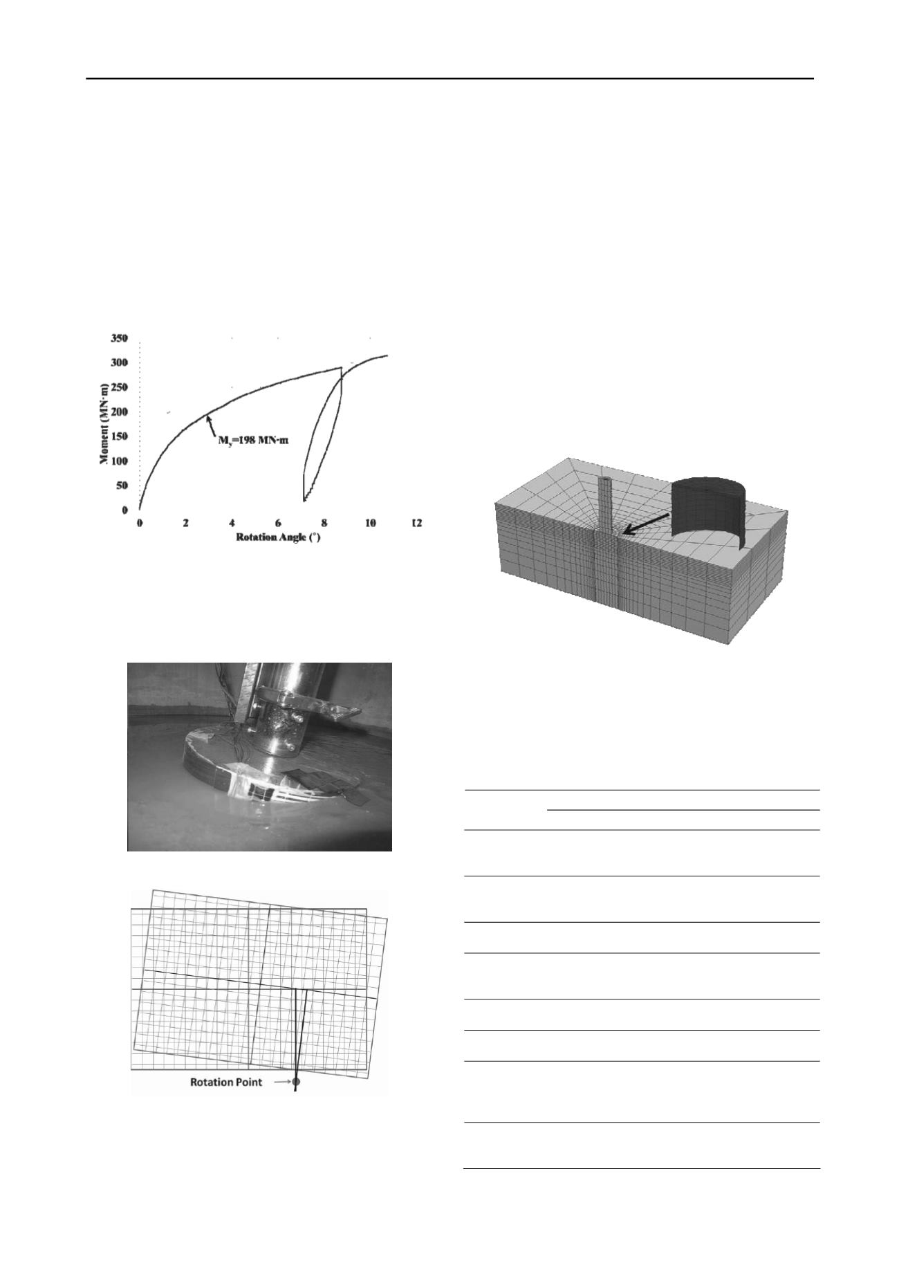
The load – displacement curve of the test are shown in figure
2. The load is presented in moment, which is the horizontal load
multiplied by the vertical eccentricity of the load from the
foundation top. The displacement is shown in terms of the
rotation of the foundation. Gradual decrease in the slope was
observed and the method by Villalobos (2006) was used to
define the yield load, which was 198 MN-m.
Figure 2. Moment – rotation angle curve of the centrifuge test
The model and nearby soil after the test are shown in Figure
3. Tilting of the foundation by the horizontal and moment load
induced several mm of heave in the passive side and 20 to 30
mm of subsidence behind the bucket. Positions of the model
before and after the load test are shown in Figure 4.
Figure 3. Model and nearby soil after the test
Figure 4. Comparison between positions before and after the test
3 NUMERICAL ANALYSIS
3.1
Model setup and analysis procedures
Numerical modeling in this study was performed using FLAC
3D V 5.0 based on the finite-difference method and explicit
scheme (Itasca, 2012). The numerical model was modified from
a model used in Kim et al. (2013) and detailed descriptions are
given for modeling and analysis procedures.
Soil elements were modeled by Mohr-Coulomb failure
criterion with linear elasticity up to plastic yield and the bucket
body and tower parts were modeled by linear elastic solid
elements. In order to represent the load conditions, a solid
circular tower was additionally modeled on top of the bucket
top lid and horizontal displacement was applied on the top face
of the tower. Half section model mesh and boundary conditions
were used for the analysis because of the symmetry of the
foundations and load conditions. Approximately 4800 elements
were used in the model. Actual steel deformation properties
were used in the analysis (E = 200 GPa, ν = 0.30). The mesh for
the analysis is shown in Figure 5.
Figure 5. Mesh for numerical model (Bucket body shown in magnified
scale)
The base properties for the model are shown in Table 1. The
submerged unit weight of the steel used for the bucket body was
modified from actual value, because the weight of the centrifuge
model bucket was increased by the connection between the
bucket body and the vertical rod.
Table 1. Base properties for numerical analysis
Parameters
Items
Bucket
SM Layer
ML Layer
Submerged
unit weight
(γ
sub
, kN/m
3
)
75.9
9.50
8.60
Elastic
modulus (E,
MPa)
200,000
10
10
Poisson ratio
(ν)
0.3
0.3
0.3
Internal
friction angle
(φ)
-
33.7
34.5
Dilation angle
(ψ)
-
11.7
0
Cohesion (c,
kPa)
-
16.1
5.2
Friction angle
between
bucket wall
and soil (δ, )
-
22.5
-
Coefficient of
earth pressure
at rest (K
0
)
-
0.5
0.5


