2365
Technical Committee 209 /
Comité technique 209
looks like that two different mechanisms are active which are
not comparable.
4 NUMERICAL INVESTIGATIONS
4.1
General
The experimental works were further investigated by finite
element calculations. The experimental test loadings as well as
test loadings with bigger pile diameter were recalculated. The
numerical calculation software PLAXIS 2D - Version 9.0 was
used. A rotation-symmetric, 2-dimensional FE-model was built.
The simulation of the soil displacement during jacking was
considered by the method of Dijkstra et al. 2006. A detailed
calculation description and the verification of the numerical
model is given in Lüking 2010.
Finally the numerical results confirmed the results of the
experimental tests quantitatively and qualitatively.
4.2
Results of the numerical calculations
Figure 5 shows the distribution of the inner skin friction for
different inner pile diameters (D
i
= 0.45 m up to D
i
= 3.95 m) of
a pile which is embedded in the soil of about d
e
=10 m. The soil
is non-cohesive and has a “dense” relative density (cone
penetration resistance of about q
c
≈ 20 MPa). The settlement for
the mobilization of the skin friction was about s = 4.2 cm.
10
8
6
4
2
0
pile length [m]
0 100 200 300 400 500
inner skin friction q
is
[kN/m
2
]
D
i
= 0.45 m
D
i
= 0.95 m
D
i
= 1.45 m
D
i
= 1.95 m
D
i
= 2.95 m
D
i
= 3.95 m
Figure 5. Distribution of the inner skin friction q
is
under variation of the
inner pile diameter D
i
at a pile embedded length of d
e
= 10 m and a pile
settlement of about s = 4.2 cm
At low pile diameter (D
i
= 0.45 m) the results show a good
agreement in the distribution to the experimental works,
compare Figure 3 with Figure 5.
Furthermore the results show that the inner skin friction for
lower pile diameters is significantly higher at a length of
approximately two pile diameters. On the upper part of the pile
length no skin friction was mobilized. With an increasing pile
diameter the peak value of the skin friction is reduced and is
transferred to the upper part of the pile. At pile diameters of
about 3 m or 4 m the distribution of the inner skin friction is
comparable to the outer skin friction. The changeover from a
raised inner skin friction to a more constant inner skin friction is
continuous. Calculations show that this changeover depends
mainly on the pile diameter and the relative density of the soil,
see Lüking 2010. The distribution of the inner skin friction is
also valid at “loose” relative density (q
c
≈ 10 MPa).
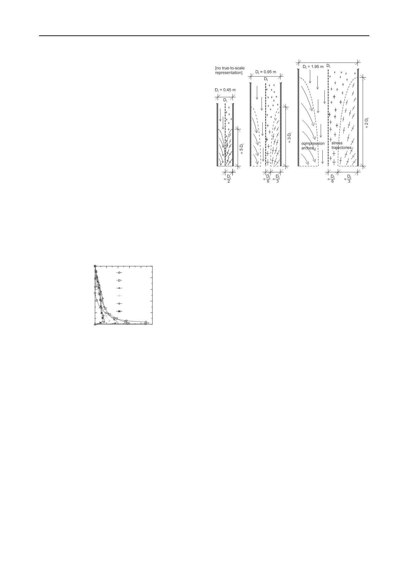
Figure 6 shows the numerical results for the orientation of
the stress trajectories and for the load transfer depending on the
pile diameter in a “dense” relative density of a non-cohesive
soil. The left part of each pile shows the derived load transfer
based on the stress trajectories which are shown on the right
part. In general all results show a rotation of the stress
trajectories near the pile toe and also at the pile wall. With
increasing distance from the pile wall to the middle of the soil
plug the rotation is reducing. Also this depends mainly on the
pile diameter.
Figure 6. Numerical results for the orientation of the stress trajectories
(right part of each pile) and the derived load transfer (left part of each
pile) for different pile diameters in a "dense" relative density of a non-
cohesive soil
The orientation of the stress trajectories suggests a
compression arch, which is in analogy to the load transfer
mechanism of the outer skin friction, see Kempfert 2009.
At low pile diameters these compression arches can be
overlapped and results in another support. Because of this the
inner skin friction can increase significantly which is also
shown in the numerical and experimental results, compare
Figure 5 and Figure 3. With increasing pile diameter the height
of the compression arches is also increasing. This load transfer
could also be identified in “loose” relative density.
Finally the results suggest that the load transfer takes place
over an inner skin friction which is based on compression
arches inside the soil. No fully plugged soil inside an open-
ended displacement pile could be identified which would
legitimate to treat the plug in a monolithic way.
5 CALCULATION METHODS
5.1
General
Based on the new knowledge two feasable methods for
calculating the bearing capacity of open-ended displacement
piles are suggested. The values were verified statistically to a
large extend with calculation method 1 up to a pile diameter of
D = 1.6 m in cohesive and non cohesive soils and with
calculation method 2 up to a pile diameter of D = 1.2 m in non-
cohesive soils. All histograms of the statistical verifications can
be found in Lüking 2010.
5.2
Calculation Method 1
Calculation method 1 is based on an analysis of 28 static and 59
dynamic pile loading tests with pile diameters up to D = 1.6 m.
This method derived new adaptation factors which are linked to
the values of experience of the EA-Pfähle 2012. The basic
equation for calculating the pile resistance is given in Eq.3.
s ks s b kb b k
A q A q R
,
,
(3)
R
k
: characteristic pile resistance
b
: adaptation factor for the pile toe, see Eq.4
q
b,k
: characteristic pile toe pressure after EA-Pfähle 2012
A
b
: pile base area (contact area of the pile and the
bottom area of the soil plug)
s
: adaptation factor for the pile skin, see Eq.5
q
s,k
: characteristic pile skin friction after EA-Pfähle 2012
A
s
: outer shaft area of the pile


