2372
Proceedings of the 18
th
International Conference on Soil Mechanics and Geotechnical Engineering, Paris 2013
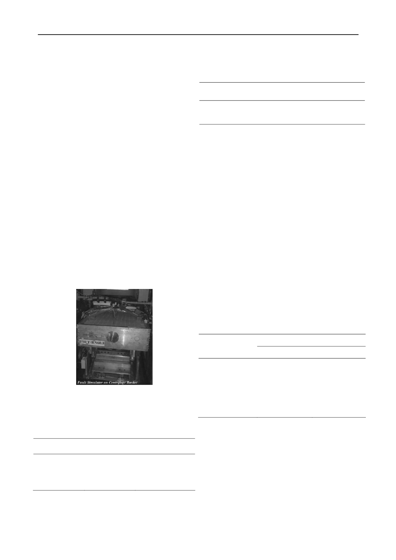
this study. Outer dimensions of the box are 102×76×68 cm
(l×w×h) and the inner dimensions are 96×70×23 cm. The split
line of the box which is the faulting line itself, makes the angle
of 30˚ from the vertical direction. The box setup is assembled
and fixed on a 4 cm thick aluminum block of 15 cm width that
can bear the hydraulic jack caused 5 ton horizontal force and
high magnitude vertical force which is exerted due to high
accelerations. Holes have been cut in the two ending walls of
the box as the backrests for studied structures such as pipelines.
Regarding lack of space in the centrifuge basket, the motivating
system and the other constituents of the simulator must occupy
the minimum space possible.
Moving mechanism has been designed to be enough stable
during the faulting movement and also can bear the high
magnitude unbalanced forces derived from soil-structure
friction.
A wedge-sliding mechanism has been applied for the box
movement to direct the faulting through the 30˚ specified
direction and prevent form any strike between fixed and moving
parts of the split box. The wedge-sliding mechanism is
consisted of two rails installed with the angle of 30˚ from the
vertical direction and high level force tolerating ball bearings to
guide the movement as desired. Sliding the wedge forward and
backward, the moving part of the box would have an upward-
downward movement (Fig. 4). Considering the high magnitude
forces and weight increase in high order accelerations, the
moving system has been chosen of hydraulic type to be strong
enough and less space occupying. The velocity and
displacement control can be done by means of electronic
hydraulic valves with a satisfactory level of accuracy and
reliability. The hydraulic pressure generator is installed out of
the centrifuge basket to save a significant amount of space and
is connected to the inside basket moving system by means of
hydraulic pipe and rotary joints.
Figure 4. General View
1.2
Scaling laws
The scaling laws used for this modeling are indicated as
below (Table 2).
Table 2. Scaling laws for centrifuge testing
Parameter
Model / Prototype
Dimensions
Length
1/N
L
Strain
1
1
Stress
1
ML-1T-2
Acceleration
N
LT-2
Axial Rigidity
1/N2
MLT-2
Flexural Rigidity
1/N4
ML3T-2
1.3
Soil properties
Soil material used in first test is chosen to be the granular
soil of standard Firoozkouh 161 sand. Soil material used in
second test is high porosity gravel with low density. The density
of low-density soil is equal to 50% of Firoozkouh soil density.
(Table 3)
Table 3. Properties of Firoozkouh and low-density Soil
C
c
C
u
FC
D50
(mm)
e
min
e
max
G
s
Sand type
0.88
2.58
1 %
0.27
0.548
0.874
2.65
Firoozkouh
161
-
-
~0% 3
-
-
1.3
Low-Density
1.4
Instrumentation
Two types of instruments containing strain gauge and linear
variable differential transformers (LVDTs) were installed in the
model. The strain gauges are installed in axial and
circumferential directions on the
pipelines with the number of 26 in 7 stations. Strain gauges
are placed in a way that axial and bending strains could be
measures separately. Strain gauges are of the high strain type
and are connected in the quarter bridge form.
Three LVDTs of the whole 5 ones are installed on the
surface of the pipeline to record the deformation profile and the
2 other ones measure the axial displacement of the two endings
of the pipeline. Apart from above, colorful grids were being
used on the surface and between the soil layers.
2 RESULTS
Two tests were conducted in this study. In the first one, a
stainless steel pipe with diameter of 8.0 mm and wall thickness
of 0.4 mm which buried in Firoozkouh sand was subjected to a
70 mm reverse faulting with the acceleration of 40g. In the
second experiment, the stainless steel pipe with 8.0 mm
diameter and 0.4 mm wall thickness which buried in low-
density gravel was subjected to the reverse faulting with 40g
acceleration. The properties of model and prototype are
indicated in Table 4.
Table 4. Properties of model/prototype for conducted tests
1st Test
2nd Test
Model
Prototype
Model
Prototype
Pipeline Diameter (m)
0.008
0.320
0.008
0.32
Pipeleine Wall
Thickness (m)
0.0004
0.016
0.0004
0.016
Faulting Magnitude (m)
0.070
2.8
0.070
2.8
Backfill
Firoozkouh 161
High Porosity Sand
(Low Density)
Faulting Type
Reverse (60%)
Reverse (60%)
Following figures illustrate the deformations of pipeline and
soil during the faulting process. In Figs. 9 and 10 bending and
axial strains before pipe failure versus distance from the faulting
in 2nd test are presented.


