2348
Proceedings of the 18
th
International Conference on Soil Mechanics and Geotechnical Engineering, Paris 2013
Figure 1. Problem statement.
3 FINITE ELEMENT MODELLING.
ABAQUS 6.10 EF-1 is used in the present finite element
analysis. As the embedment of pipe in the seabed is large
deformation problem, the conventional finite element
techniques in Lagrangian approach cannot simulate the
complete process realistically as numerical difficulties are
generally encountered for such large displacements. Therefore,
in this study the Coupled Eulerian Lagrangian (CEL) technique
currently available in ABAQUS FE software is used. In CEL,
the soil flows through the fixed mesh without having any
numerical issues. The FE modeling using CEL for pipe
embedment into the seabed is presented by the authors
previously (Dutta et al. 2012 a&b). A soil domain of 8m×3m
×0.04m (length × height × thickness) is used in this study. The
soil is modelled as Eulerain elements and the pipe is modelled
as Lagrangian elements. The 1.5 m void space above the soil is
required to accommodate the displaced soil mass (Eulerian
materials) during pipe displacement. Zero velocity boundary
conditions are applied at all faces of the Eulerian domain to
make sure that Eulerain materials are within the domain and
cannot move outside. However, at the seabed-void interface, no
boundary condition is provided so that the soil can flow to the
void. That means, the bottom of the model is restrained from
any vertical movement, while all the vertical faces are restrained
from any lateral movement. The pipe is modeled as a rigid
body. During penetration, especially in cyclic loading, the
remolding of soil near the pipe could cause significant reduction
in undrained shear strength. Smooth pipe/soil interface
condition is used for the present analysis. Mesh sensitivity
analysis is also performed and an optimum mesh size of
0.04m×0.04m is used (Dutta et al. 2012 a).
The loading is performed in three different stages. First, the
geostatic conditions are applied to bring the seabed to in-situ
condition. Second, the pipe is penetrated applying a vertical
load (
p
) which is the combined effect of submerged unit weight
of the pipe and laying effects. In the third step, 40 cycles of
small amplitude (
0.05
D
) lateral displacement are applied using
displacement boundary conditions under the constant vertical
load
p
0
. Plastic shear strain develops near the pipe during
penetration. In the present FE analyses the degradation of
undrained shear strength as a function of plastic shear strain is
adopted using the following model (Einav and Randolph 2005
Wang et al. 2009 and Zhou and Randolph 2009).
s
u
=[
rem
+(1-
rem
)exp(-3
/
95
)]
s
u
0
(1)
where
t
rem
S
1
,
S
t
is the soil sensitivity,
is the
accumulated equivalent plastic shear strain,
s
u
0
is the intact
undrained shear strength of soil and ξ
95
is the accumulated
plastic shear strain at 95% undrained shear strength degradation.
The variation of
s
u
0
with depth is shown in Fig. 1 and the von-
Mises yield criteria is adopted.
In this study four cases are simulated and the results are
compared with centrifuge test results of Cheuk and White
(2008). Two tests (KC-04 & KC-05) are in kaolin clay and two
(HP-06 & HP-07) are in high plasticity clay. Table 1 shows the
parameters used in the FE analyses. The vertical load
p
for
initial static penetration and during cyclic motion are also
shown in Table 2.
Table 1. Parameters for finite element modelling.
Pipe
Pipe diameter,
D
(mm)
Lateral displacement during cyclic motion
800
± 0.05
D
Soil Properties
Kaolin
Clay
High
Plasticity
Clay
Undrained modulus of elasticity,
E
u
500
s
u
500
s
u
Poisson’s ratio,
u
0.495
0.495
Undrained shear strength at mudline,
s
um
(kPa)
0.75
0.40
Gradient of shear strength increase,
k
(kPa/m)
1.6
2.5
Submerged unit weight of soil,
(kN/m
3
)
Remoulded soil sensitivity,
S
t
Accumulate absolute plastic shear strain
for 95% degradation of soil strength,
95
6.0
4.0
10
3.0
1.7
10
Table 2. Centrifuge test conditions (Cheuk and White 2011).
KC-04 KC-05 HP-06 HP-07
Pipe vertical load,
p
(kN/m)
1.17
2.23
1.47
2.61
Initial static embedment,
w
in
/
D
0.08
0.12
0.10
0.22
Pipe vertical load at cyclic motion,
p
0
(kN/m)
1.13
2.17
1.43
2.52
4 RESULTS.
The pipe was initially penetrated under a static vertical load
p
.
The initial static embedment (
w
in
)
for this load is shown in Table
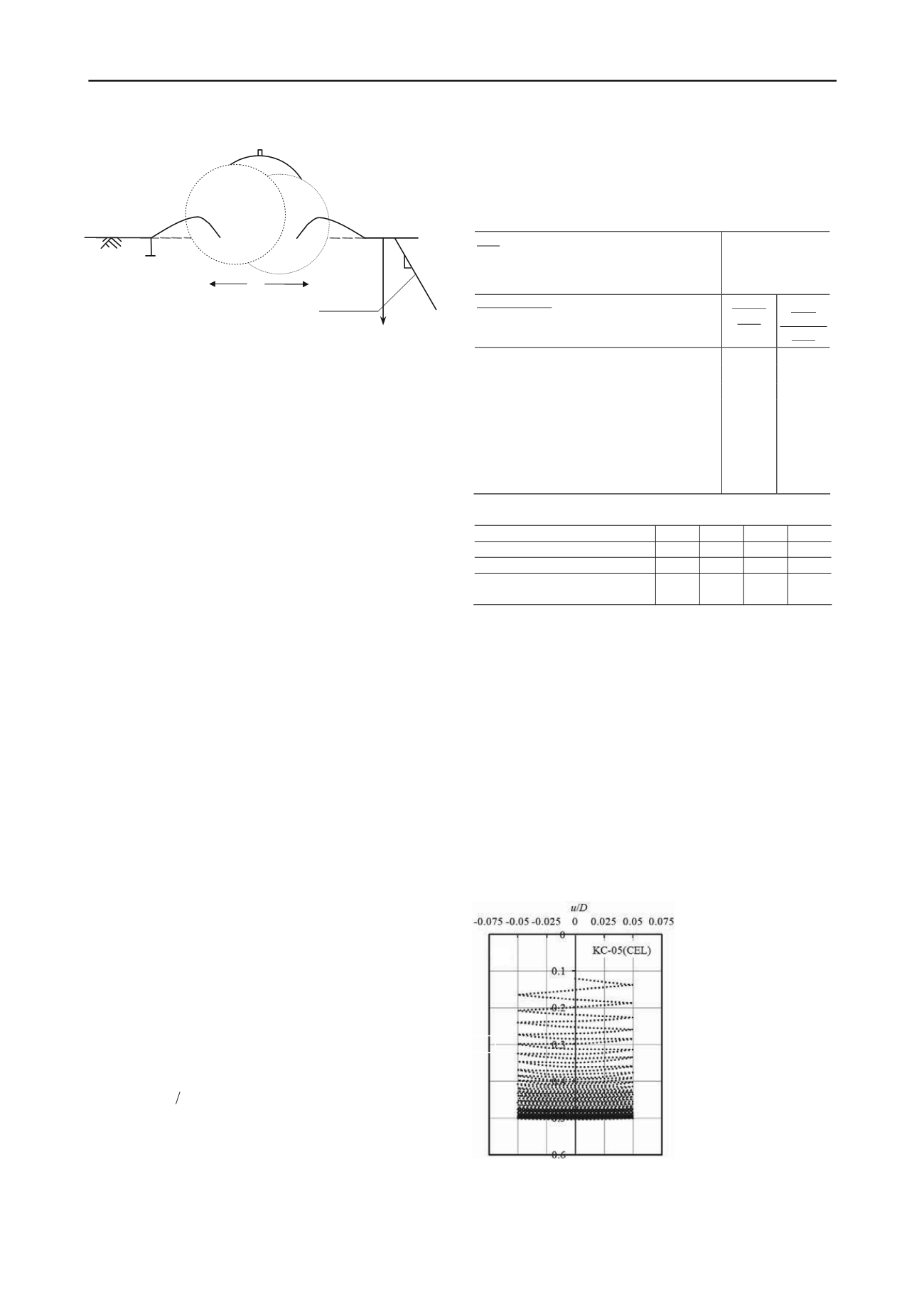
2. After initial penetration a small amplitude cyclic lateral load
is applied (e.g. Fig. 2 for KC-05,
u =
pipe lateral displacement)
to simulate the first 40 cycles (Stage-I) of centrifuge tests. The
normalized lateral resistance for KC-05, where
s
u
0(
i
)
in the
horizontal axis is the intact undrained shear strength at pipe
invert, is shown in Fig. 3(a) and comapred with centrifuge test
results Fig.3(b). The lateral resistance is slightly higher than that
obtained in centrifuge test. This might be due to the limitation
of the soil shear strength degradation model (Eq. 1). It is very
difficult to measure and model the behaviour of soil near the
pipeline under cyclic loading. However, using this simplified
model (Eq. 1) in ABAQUS CEL the lateral resistance during
cyclic movement is reasonably simulated.
Figures 4(a),4(b) and
4(c) show the lateral
resistance for other three
simulations. As shown,
the shape of the lateral
resistance plot is different,
which mainly depends on
soil shear strength profile,
shear
strength
degradation, sensitivity of
soil, and applied vertical
load. The depth of the
invert
of
the
pipe
normalized
by
pipe
diameter (D) with number
of load cycle is shown in
Fig. 5 for comparison the
centrifuge test. the present
FE model reasonably
simulates the embedment
of the pipe with the soil parameters listed in Table 1. Figure 5(a)
shows that the depth of embedment does not increase
x
Z
x
z
D
p
0
P
B
ipe
s
u0 =
s
um
+
kz
w
erm
S
S
Stage-I
tage-II
tage:-III
s
k
um
w
/
D
Figure 2. Pipe embedment during lateral
motions


