2344
Proceedings of the 18
th
International Conference on Soil Mechanics and Geotechnical Engineering, Paris 2013
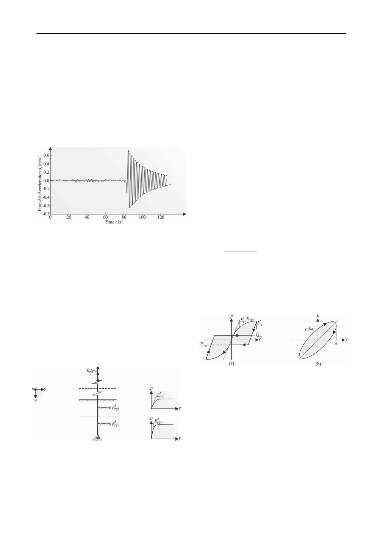
from the acceleration decay when the turbine generator shuts
down and the blades pitch out of the wind, see Figure 1. Hence,
assuming that the wind turbine structure behaves as a single-
degree-of-freedom (SDOF) system, the eigenfrequency
f
1
and
modal damping δ
1
are determined by least-squares fitting of a
linear function to the zero crossings and to the natural logarithm
of the rate of decay of the vibration, respectively. It should be
noticed that a wind turbine structure has two closely spaced
modes occurring at nearly identical frequencies (Damgaard
et
al.
2012), where vibrational energy is transferred from the
highest to the lowest damped mode. Hence, for the damping
estimation of each free vibration test it is ensured that the
acceleration of the structure only takes place in the fore-aft
direction
y
.
Figure 1
. Raw output acceleration signal during a “rotor
-
stop”.
3.1 Winkler Approach
Offshore wind turbines supported by pile foundations are
subjected to lateral cyclic loads. The load-deflection behaviour
is often evaluated by a Beam on Nonlinear Winkler Foundation
(BNWF) model due to its computationally efficiency and
practical versatility. The tower and pile are modelled as
Bernoulli-Euler beams and the soil-structure interaction is
incorporated via so-called
p-y
curves suggested by DNV 2011,
see Fig. 2. The soil consists of a series of independent soil
layers with smooth horizontal boundaries,
i.e.
no shearing can
be transmitted across the boundaries. Rather than modelling the
soil as a number of discrete springs connected to the element
nodes, this paper uses a consistent approach, where the soil is
modelled as a continuous spring over each element. The nodal
forces are then obtained via numerical integration. The reader is
referred to Damgaard
et al
. 2011 for more information about the
computational model.
Figure 2. Beam on nonlinear Winkler foundation (BNWF) model.
3.1.1 Soil Damping Estimation
In general, attenuation of wave propagation in the soil is
determined from geometric damping,
i.e.
the radiation of waves
into the subsoil, and material damping caused by the slippage of
soil grains with respect to each other. However, extensive
studies of wind turbines on a homogeneous or layered ground
made by Andersen 2008 show that geometric dissipation is
insignificant at frequencies below 1 Hz. From the continuum
mechanics it is known that material damping is related to the
relative motion of material points, and the energy dissipation is
frequency-dependent. For a given frequency and deformation
level, the soil material damping can be approximated to an
equivalent viscosity. Based on a static deformation analysis,
using the Winkler approach, the following procedure is used to
determine the
soil damping ratio ζ
soil
of the lowest eigenmode
Φ
(1)
:
A 10-minutes time-domain simulation of the wind turbine
structure is conducted for a power production situation with
a normal turbulence model (IEC 2005) using the aeroelastic
code FLEX (Øye 1996). A correct estimate of the structural
eigenfrequency
f
1
in the FLEX model is ensured by
extending the tower until the eigenfrequency
f
1
of the
Winkler model is reached.
Based on the maximum overturning moment at the
tower/foundation interface from the FLEX simulation and
including wave loads, the horizontal pile deformation in
each nodal point below the seabed is evaluated.
Assuming a load-displacement cycle after the generator
shuts down, as indicated in Figure 3a, the irreversible soil
deformations are a measure of energy dissipation. Hence, the
energy dissipation in Figure 3a can be transformed to an
equivalent viscous damping model as shown in Figure 3b.
Using the theory of linear structural dynamics, the soil
damping ζ
soil
of the lowest eigenmode
Φ
(1)
: is determined from
the global damping matrix
C
, the angular eigenfrequency ω
1
,
the eigenmode
Φ
(1)
and the modal mass
M
1
given by
1 1
(1)
(1)T
soil
2
M
C
Φ Φ
(1)
The virgin curve in Figure 3a is determined by the
p-y
curve
formulation given by DNV 2011. The unloading phase is
determined by the initial stiffness
E
*
py
. Assuming separation
between the pile and the soil, a shear drag
p
drag
is introduced.
For cohesionless soils, the shear drag depends on the vertical
eff
ective stress σ
´
v
(Ovesen
et al.
2006) given by
p
drag
=0.6
D
σ
´
v
,
whereas for cohesive soils the undrained shear strength
c
u
must
be considered,
i.e. p
drag
=0.7
Dc
u
.
Figure 3. Hysteresis Loop Method (Nielsen 2004): (a) Load-
displacement curve after the wind turbine generator shuts down, (b)
Hysteresis loop implied by viscous damping in a harmonic motion with
the amplitude A and the angular eigenfrequency ω
1.
4 INTERPRETATION OF RESULTS
Experimental modal testing of 30 offshore wind turbines in the
period 2006-2011 is presented in Figure 4a and Figure 4b in
terms of the modal damping δ
1
and the eigenperiod
T
1
of the
lowest eigenmode
Φ
(1)
, respectively. Using a lognormal
probability distribution, the 5% quantile of the modal damping
δ
1
and the eigenperiod
T
1
are estimated to 0.11 and 2.94 s,
respectively. This corresponds to an eigenfrequency
f
1
of 0.34
Hz. As indicated in Figure 4a and Figure 4b, the scatter of the
estimated parameters is high. Increasing the R-square value
from 0.95 to 0.99, meaning that the fit of the acceleration
amplitude peaks and zero crossings explains 99% of the total
variation in the data about the average, seems to reduce the
scatter to a certain extent, see Figure 4c and Figure 4d. Overall,


