2342
Proceedings of the 18
th
International Conference on Soil Mechanics and Geotechnical Engineering, Paris 2013
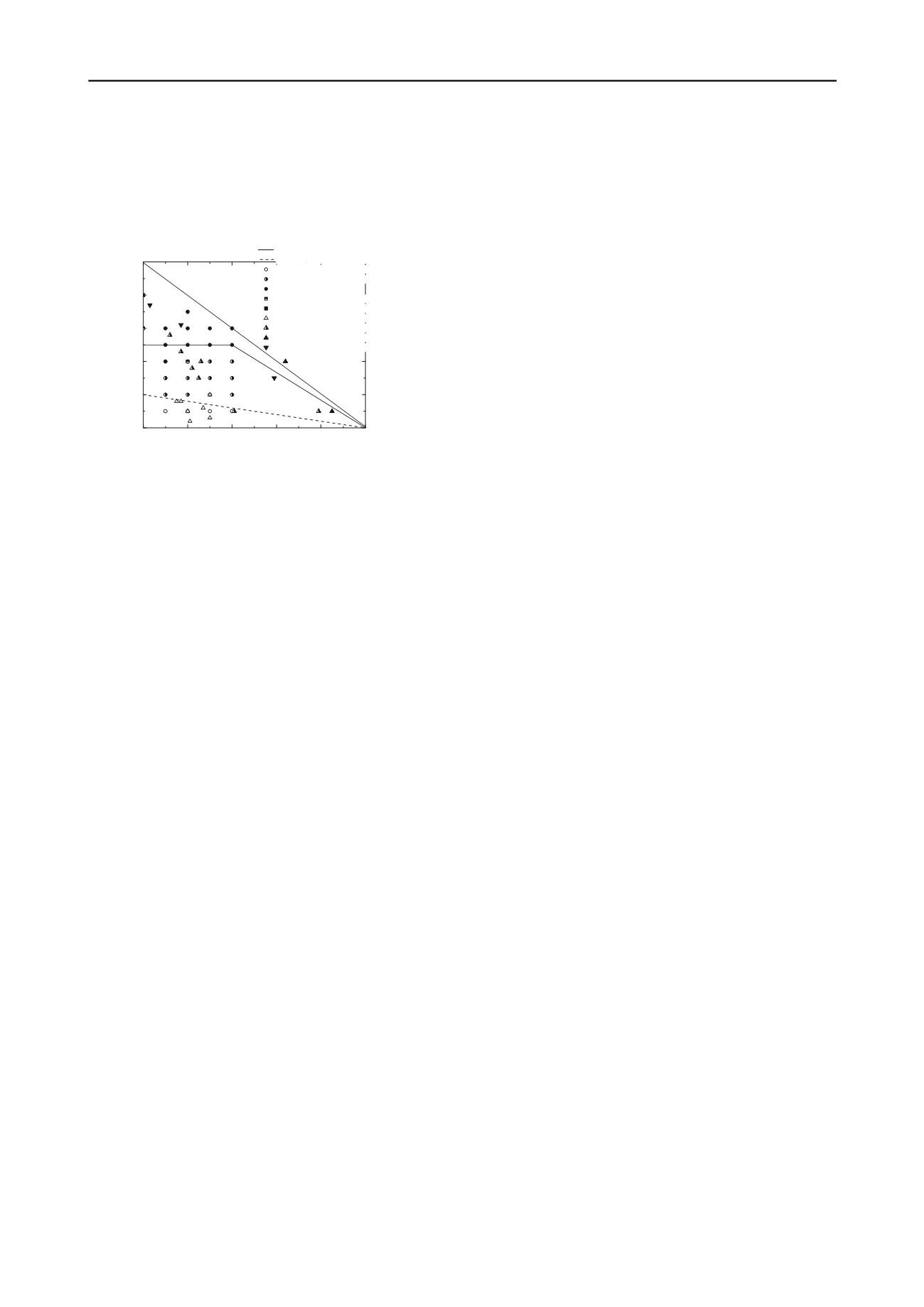
(2) A serviceability region II in which the cyclic loading
has some influence on the pile response and the displacement
response can be identified as “continuing displacement”.
(3) A unstable region III in which cyclic loading causes
severe damage for the pile to produce very large permanent
displacement and in some cases a plunging failure occurs.
0.0
0.2
0.4
0.6
0.8
1.0
0.0
0.2
0.4
0.6
0.8
1.0
S
D
C
B
III
II
I
Proposed lower boundary of unstable zone
Proposed upper boundary of stable zone
Test results - no accumulated displacement
Test results - continuing displacement
Test results - failure
McAnoy et al. (1982) - continuing settlement
McAnoy et al. (1982) - failure at N=564
Stevens (1978) - no settlement
Stevens (1978) - continuing settlement
Stevens (1978) - plunging failure
Karlsrud et al. (1986) - failure after 100 cycles
Cyclic load ratio (CLR)
Static load ratio (SLR)
zone I: Stable
zone II: Serviceability
zone III: Unstable
A
Figure 6. Cyclic deformation diagram for pile in silt (
N
=50,000)
The upper boundary to the cyclic permanent displacement is
the straight line (CS: SLR+CLR=1) that represent the
combinations of SLR and CLR necessary to cause a failure of
pile without cyclic effects being considered. The other two lines
plotted in this diagram represent the approximate boundaries
between the stable region, the serviceability region and the
unstable region. These lines are defined by the following
relations:
Upper boundary of stable zone (line AB and BC):
0.5
0
0.4
1.2
1 0.4
1.0
CLR
SLR
CLR SLR
SLR
(7)
Lower boundary of unstable zone (line DC):
5
1,
0
1
CLR SLR
SLR
(8)
Fig. 6 also plots the other test results of field or model tests
on axial cyclically loaded pile. It can be seen that these
proposed lines are consistent with the experimental data and
thus it is indicated that the proposed three regions are capable of
reasonably identifying the deformation behavior of pile under
various load combinations. A diagram such as shown in Fig. 6
represents the permanent displacement of a pile for a specified
number of cycles,
N
. As
N
increases, the stable region will
remain unchanged and the unstable region may increase as the
permanent displacement increases.
In the pile design, it is very convenient to determine the
deformation behavior of the pile to cyclic loading using this
diagram. The most conservative design is to have the cyclic
loads in the stable region which means that pile will not be
affected by cyclic loading and issues of the permanent
displacement can be totally ignored. If the designed cyclic load
is in the serviceability region, the permanent displacement
accumulates in “stable” way and depends on both of the number
of cycles and the load characteristics; and it can be predicted
using the proposed simple method mentioned above. For a safe
design, it should avoid the cyclic load to be in the unstable
region in which cyclic loading will result in very large
permanent displacement and even a plunging failure.
5 CONCLUSION
A series of tests were conducted on large-scale model piles
subjected to long-term cyclic axial loading. The deformation
behavior of the piles in silt to cyclic loading was investigated.
The evolution of permanent displacement highly depends on
the magnitude of cyclic load. In general, the accumulation of
permanent displacement increases with increasing cyclic load
amplitude and increasing number of cycles. However, the pile
behaves in an elastic manner and does not accumulate any
deformation after the first few cycles of loading if the
magnitude of cyclic load is less than 10% of the ultimate pile
capacity. Very large permanent displacement, even plunging
failure, occurs when magnitude of cyclic load exceeds 50% of
the ultimate pile capacity. This suggests that the magnitude of
the cyclic load be kept below 50% of the ultimate capacity to
avoid large permanent displacement in the design.
These results provide a better understanding of the
deformation behavior of pile in silt to long-term cyclic axial
loading, and can be used to optimize the designs of pile
foundations that resist cyclic loads in service.
6 ACKNOWLEDGEMENTS
The work was supported by the National Natural Science
Foundation of China (Grant Nos. 51225804 and U1234204).
7 REFERENCES
ASTM 2010. D2487-10. Standard Practice for Classification of Soils for
Engineering Purposes (Unified Soil Classification System). ASTM
International.
Briaud J.L and Felio G.Y. 1986. Cyclic axial loads on piles: Analysis of
existing data. Canadian Geotechnical Journal, 23, 362-371.
Chan S.F. and Hanna T.H. 1980. Repeated loading on single piles in
sand. Journal of Geotechnical Engineering Division, 106, 171-188.
Karlsrud K., Nadim F. and Haugen T. 1986. Piles in clay under cyclic
axial loading-field tests and computational modeling. Proc., 3rd Int.
Conf
., Numerical Methods in Offshore Piling, Nantes, France, 165-
190.
Karlsrud K., Nowacki F. and Kalsnes B. 1993. Response in soft clay
and silt deposits to static and cyclic loading based on recent
instrumented pile load test. Proc. SUT Int. Conf, Kluwer, Dordrecht,
549-584.
Lee C.Y. and Poulos H.G. 1991. Tests on model instrumented grouted
piles in offshore calcareous soil. Journal of Geotechnical
Engineering, 117, 1738-1753.
McAnoy R.P.L., Cashman A.C. and Purvis D. 1982. Cyclic tensile
testing of a pile in glacial till. Proc., 2nd
Conf
., Numerical Methods
in Offshore Piling, Austin, Tex., 257-292.
O’Riordan N., Ross A.
and Allwright R. 2003. Long-term settlement of
piles under repetitive loading from trains. Transportation
geotechnics, Thomas Telford, London, 67-74.
Poulos
H. G. (1988). “Cyclic stability diagram for axially loaded piles.”
Journal of Geotechnical Engineering, 114, 877-895.
Poulos H.G. 1989. Cyclic axial loading analysis of piles in sand. Journal
of Geotechnical Engineering, 115, 836-852.
Stevens J.B. 1978. Prediction of pile response to vibratory loads. Proc.,
10
th
OTC
Conf
., Houston, Tex., Vol. 3, 2213-2223.


