2054
Proceedings of the 18
th
International Conference on Soil Mechanics and Geotechnical Engineering, Paris 2013
Construction
work zone
Water intake pipe, 2800 diameter
Water discharging pipe, 2800 diameter
Water discharging channel (RC box)
Approx. 30 m
No. 2 dust filter
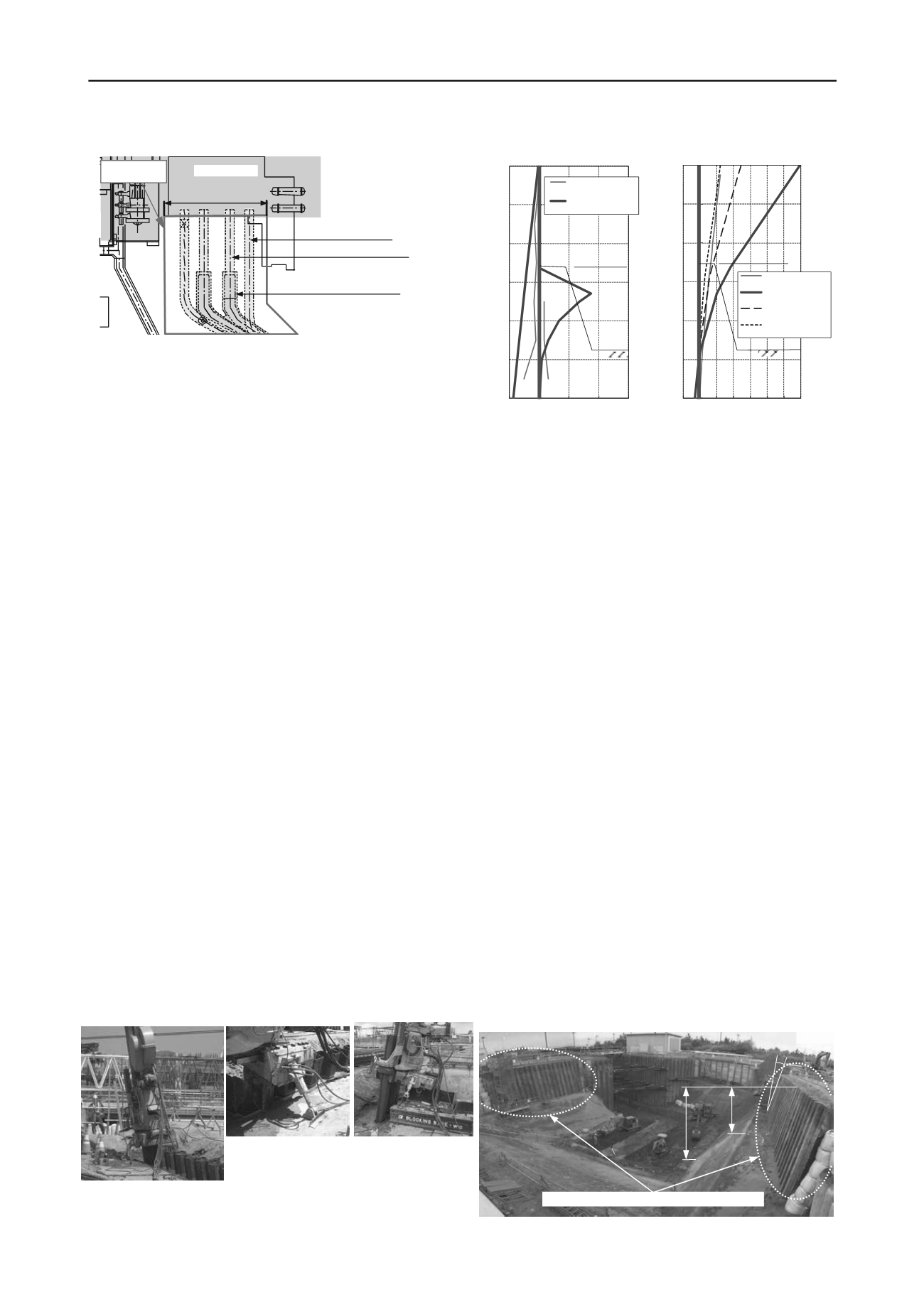
Figure 14. Earth pressure
distribution comparison
Figure 15. Retaining
wall displacement
-12
-10
-8
-6
-4
-2
0
- 50
0
50
100
150
Depth (GL-m)
Earth pressure (kN/m
2
)
Measurement results
(finalexcavation)
Design values
▽
GL-9.6m
▽
GL-5.3m
-12
-10
-8
-6
-4
-2
0
- 20 0 20 40 60 80 100 120
Depth (GL-m)
Retainingwall displacement (mm)
Measurement results
(finalexcavation)
Design values
Calculatedvalues
Calculatedvalues
▽
GL-9.6m
▽
GL-5.3m
(c=0kN/m
2
)
(c=5kN/m
2
)
(c=9kN/m
2
)
(c=0kN/m
2
)
Figure 13. Construction work zone plan
5.2
Inclined-braceless retaining wall construction method
The steel sheet piles driven in at an inclination angle were
installed in a manner similar to ordinary vertical installation: a
silent piler was used combined with a water jet to reduce the
insertion resistance. Because the piler was tilted according to
the inclination of the piles being installed, an auxiliary cylinder
was installed on the piler main unit to control the angle (Photo 2
and 3). The initial insertion until the piler was set on the piles
used a blocking base (110 kN), similar to ordinary vertical
installation. The top plate of the blocking base was inclined by
10 degree to accommodate the inclined installation of the piles
(Photo 4). The inclination angle was monitored by infrared laser
units installed at two locations aside from inclined finishing
stake.
6 CONCLUSIONS
5.3
Comparison of onsite measurement results and design
values
5.3.1
Earth pressure
The distribution of actual measurements for the earth pressure,
which was taken by wall-surface-mounted earth pressure gauges
at the time of the final excavation, indicated 20%–50% of the
design values on the back side (active side) and 5% of the
ultimate value on the excavation side (passive side) (figure 14).
The setting method for coefficient of earth pressure (applying
the Coulomb’s formula) was considered to be valid because the
gradient (equivalent to the earth pressure coefficient) up to GL-
3m was roughly equal for the active earth pressure distribution.
With regard to the passive earth pressure, the displacement of
the retaining wall was small and the ground had a sufficient
margin for resistance on the passive side.
For the inclined-braceless retaining walls (inclination of 10
degree) with an excavation depth of 9.6 m in sand ground, the
effects of earth pressure reduction and stability of retaining wall
were verified by a centrifugal model experiment. A design
method was developed that considers inclination of the wall by
using the Coulomb’s formula in elasto-plastic analysis so that
inclined-braceless retaining walls can be adopted at actual
construction sites. The actual measurement values taken onsite
for the earth pressure acting on the retaining wall and the
displacement and stress of the retaining wall both agreed with
the design values. Thus, the safety of the retaining wall can be
secured using the proposed design method. The inclined
retaining wall construction method was used to realize a
cantilever retaining wall without shoring despite a deep
excavation depth of 9.6 m. Thus, excavation, piping, and
building work can be completed in a short term and safely.
We will collect design and construction work track records
for the inclined retaining walls under a variety of ground
conditions for verification of evaluation methods for analysis
models, soil parameters, and earth pressure, and cycle time of
construction work, in order to establish more practical design
and construction methods.
5.3.2
Displacements and stresses of steel sheet piles
The maximum displacement during final excavation was
24.1mm, which was about 20% of the design value of 119.2mm
(Figure 15). The maximum stress level of the steel sheet piles
according to strain gauges was a tensile stress of 8.4N/mm
2
,
which is extremely small and about 8% of the design value of
103N/mm
2
. Furthermore, the bending moment distribution
obtained by converting the measurement data from the
inclinometers was roughly the same as the bending moment
distribution obtained from strain gauges.
7 REFERENCES
Shimada Y., Matsumoto S., Takahashi S. and Sugie S. 2010.
Centrifugal model experiments pertaining to earth pressure of sand
ground acting on cantilever retaining walls.
Proceedings of the 65
th
Annual Conference of the Japan Society of Civil Engineers,
III-456.
Shimada Y., Idemitsu M., Takahashi S. and Maeda T. 2011. Centrifugal
model experiments pertaining to earth pressure of sand ground
acting on steel sheet pile cantilever retaining walls.
46
th
Japan
National Conference on Geotechnical Engineering,
682.
Photo 3. Auxiliary
cylinder
Photo 4. Blocking
base
Photo 2. Overall view of installation work
5.3m
9.6m
10deg.
Inclined steel sheet pile, type SP-IV, 12 m length
Photo 5. Overall view of excavation completed site


