2053
Technical Committee 207 /
Comité technique 207
0
5
10
15
0
100 200 300 400 500
Depth (m)
Bending distortion (micro)
Vertical, excavation of 3.3 m depth
Vertical, excavation of 9.6 m depth
10deg.inclination, excavation of 3.3 m depth
10deg.inclination, excavation of 9.6 m depth
Active pressure
distribution
Passive pressure
distribution
Plastic zone
GL
GL
-5.27
Elastic zone
Sliding surface with
minimum safety factor
Retaining wall
0
5
10
15
0
50
100
150
Depth (m)
Earth pressure
Beforeexcavation
Excavation of 3.3 m depth
Excavation of 5.3 m depth
Excavation of 9.6 m depth
Earth pressure at rest (0.5)
Coulom'searth pressure
(kN/m
2
)
0
5
10
15
0
50
100
150
Depth (m)
Earth pressure
Beforeexcavation
Excavation of 3.3 m depth
Excavation of 5.3 m depth
Excavation of 9.6 m depth
Coulom'searth pressure
Earth pressure at rest (0.5)
(kN/m
2
)
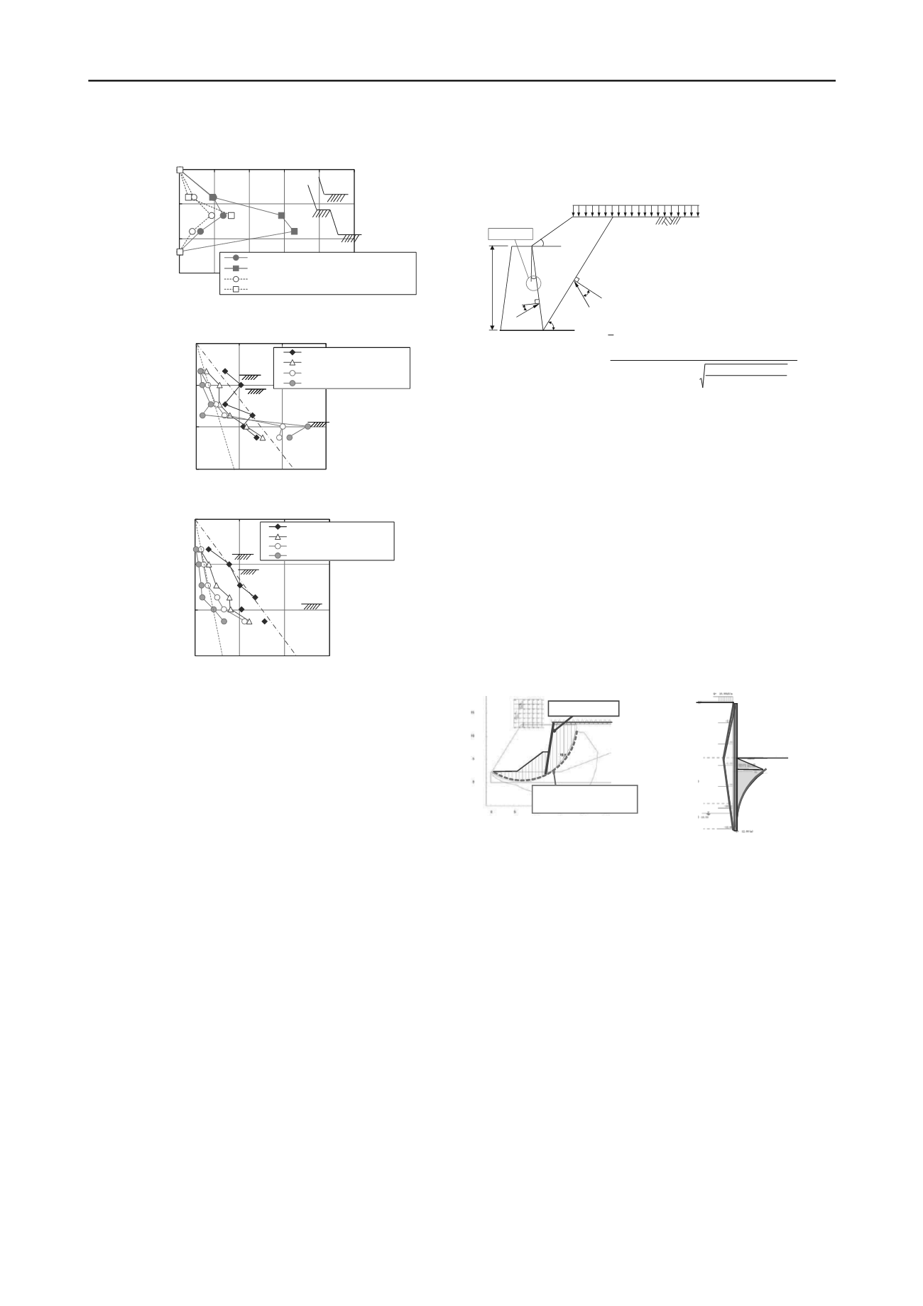
Figure 7. Bending strain distribution of retaining
Figure 8. Earth pressure acting on wall surfaces - vertical retaining walls
Figure 9. Earth pressure acting on wall surfaces - inclined retaining walls
Figures 8 and 9 show the depth distribution of the active
earth pressure that acted on the wall. Although the measurement
results for the vertically installed wall showed dispersions prior
to excavation, the validity of the earth pressure measurements
taken by this equipment were confirmed because they were
approximately equal to the earth pressure at rest assuming Ko =
0.5, as noted in the figure. The earth pressure decreased in the
excavated sections and increased more than the earth pressure at
rest in the embedded sections. The figure shows the Coulomb’s
earth pressure, where the friction angle of the retaining wall was
considered to be φ/3. The active earth pressure measured at the
excavated sections was slightly smaller in distribution than the
Coulomb’s earth pressure. The earth pressure acting on the
inclined wall decreased more than the earth pressure at rest
regardless of depth. Thus, the acting pressure was smaller than
that of the vertically installed wall, which confirmed that
inclination of the wall contributed to the stability of the wall in
terms of earth pressure as well.
4 DESIGN OF INCLINED-BRACELESS RETAINING WALL
4.1
Calculation method for earth pressure
Ground of the site (Figure 3) was a landfill comprised primarily
of loose fine sand (layer thickness: 12 m, N-value: 3–5, and φ:
33°). The inclination of the retaining wall could not be
considered in the conventional design of the temporary
retaining walls, because the Rankine–Resal formula is generally
applied to the active earth pressure used. The earth pressure
calculation method with Coulomb’s formula (Figure 10) used in
the design of permanent retaining walls, which considers the
inclination of the wall, was therefore applied. Its use was
determined safe for design purposes because the earth pressure
reduction effect was confirmed in the centrifugal model
experiments with inclined walls. Similarly, the Coulomb’s earth
pressure was adopted for the passive earth pressure.
H
α
β
δ
P
A
ω
φ
R
3
Figure 10. Active earth pressure calculation
4.2
Calculation method for embedding lengths
The embedding length was calculated using not only the
“method for determining embedding length to maintain balance
based on earth pressure” but also the “overall slippage including
the retaining wall.” The circular slipping calculation (Figure 11)
was performed to determine the embedding length so that both
of the above methods were satisfied. The safety factor for the
arc slipping calculation was set to 1.2.
4.3
Calculation of retaining wall displacements and stresses
The displacements and stresses that occurred with the retaining
wall were calculated based on elasto-plasticity analysis, which
evaluated the earth pressure and wall embedding length given in
subsections 4.1 and 4.2 above, by considering the retaining wall
as a finite length elastic beam and ground as an elasto-plastic
spring (figure 12).
5 CONSTRUCTION WORK IMPLEMENTATION RECORD
FOR INCLINED-BRACELESS RETAINING WALLS
5.1
Summary of applied construction sites
The construction sites where the inclined-braceless retaining
walls were applied were located within premises used by
existing electric power plant and new plant construction.
Excavation work had to be performed to install two sets of
water intake and water discharge steel pipes (each pipe with a
diameter of 2800 mm) in a restricted construction work zone
with a width of 30 m (Figures 3 and 13). The period of
construction work, which included piping work, needed to be
less than six months owing to adjustments that had to be made
to accommodate the progress of the main unit construction work
being performed at new electric power plant.
In order to satisfy the above conditions, the inclined-
braceless excavation retaining wall construction method which
reduces earth pressure by inclining the wall, was adopted as it
requires no shoring, even when the excavation depth is deep.
The retaining wall was fabricated from steel sheet pile type SP-
IV, and the inclination of the retaining wall was set to 10 degree
owing to restrictions imposed within the construction work zone
and the excavation cross section necessary for piping work.
Figure 11. Verification on
slipping stability
Figure 12. Elasto-plastic analysis
α
=
-10deg.
2
2
2
2
cos
cos
sin
sin 1
cos
cos
cos
2
1
A
A
A
K
H K P
P
A:
Active earth pressure of Coulomb
K
A
: Active earth pressure coefficient of slope
α: Angle created by wall back surface and vertical plane
β: Slope angle of back ground
δ: Friction angle of wall surface
φ: Angle of shearing resistance of sand
H: Height of wall on which earth pressure acts
γ: Unit weight of soil


