2061
Technical Committee 207 /
Comité technique 207
Proceedings of the 18
th
International Conference on Soil Mechanics and Geotechnical Engineering, Paris 2013
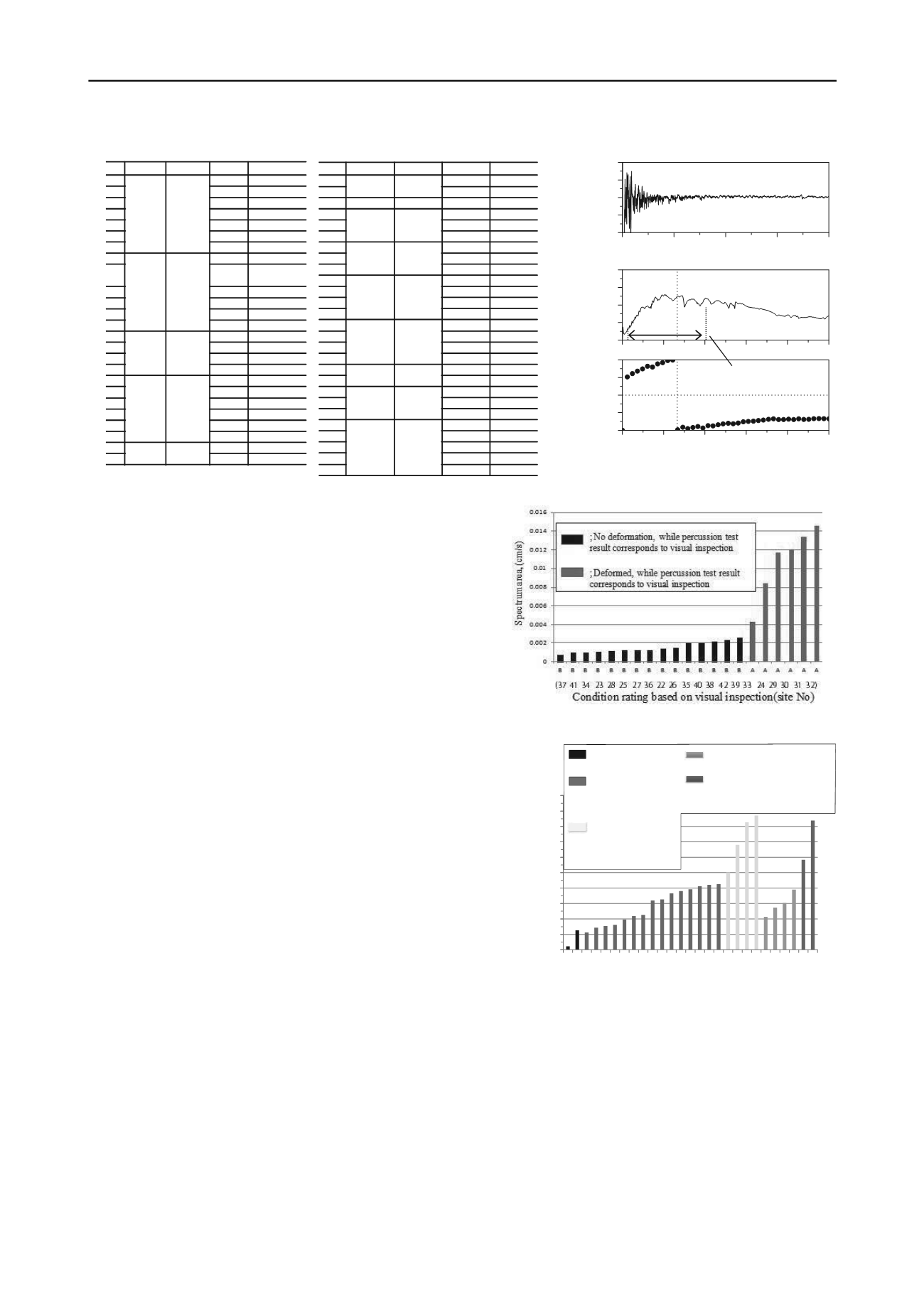
spectrum area. In the cases of ashlars wall shown in Figure 5,
the values of spectrum area Sa of retainig walls rated as
“
A(deformed)
”
were genellary larger than the ones of retainig
walls rated as
“
B(no deformation)
”
, which shows the validity of
spectrum area for the condition rating of retaining walls.
In the cases of the leaning type retainig wall shown in
Figure 6, a good corelation between the result of visually
inspected condition rating and the values of spectrum area could
not be found. In the sites No. 6, 20, 21 and 24, the values of
spectrum area was much larger than the other sites although
they were rated as
“
B (no deformation)
”
, which might imply
that the progress of the deformation at the part in which is
difficult to detect by visual inspection (e.g. subsoi, backfill, etc.).
On the other hand, at the sites 27, 26, 25 and 3, the values of
spectrum area were not necessarily larger than the other sites
although they were categorized as
“
A(deformed)
”
.
Percussion test has some problems (Nakajima et al., 2012) ;
1) heavy weight of iron ball (safety, portability) , 2) scattering
of impact force depending on inspectors (repeatability) and 3)
attenuation of inpact force especially in high frequency
range(limited range of input frequency). In applying to the
condition rating of retaining wall, second and third problems
would make it difficult to rate the condition of the retaining wall
properly especially in the case of the leaning type retaining wall.
Therefore, the authors developed a small scale exciter (Shinoda
et al., 2012), which could apply constant sweep sinusoidal
excitation under mechanically manupulation, which could solve
second and third problems. A prototype scale loading test on
leanining type retaining wall model was conducted so as to
examine the applicability of the newly developed small scale
exciter.
4 PROTOTYPE SCALE LOADING TEST
Cross section of constructed leaning type retaining wall with
height of 4.3 m and width of 1.5 m is shown in Figure 7. In
Figure 7, the outline of the develope small scale exciter is also
summarized. Retaining wall was constructed on the stiff base
layer while its backfill consisted of the cobbles, sand backfill
with degree of compaction
D
c
of 90 % and densely compacted
gravelly sand. In the loading test, the retaining wall was
subjected to the cyclic loading and unloading processes by
applying the vertical load at the surface of the backfill using the
hydraoulic jack while their amplitude were gradually increased
as shown in Figure 8. Gravelly sand layer inclined 30 degrees
from the horizontal direction so as to apply horizontal load to
the retaining wall efficently.
In the loading test, cyclic loading and unloading proccesses
were applied to the leaning type retaining wall model (Case 1).
A soil nailing reinforcement with diameter of 60 mm and length
of 4000 mm was installed after horizontal displacement at the
wall top exceeded 50 mm. As the second case (Case 2), the
model wall reinforced with the top nailing was subjected same
loading and unloading processes with Case 1. Lastly, the model
wall with top and bottom nailing, which was installed after Case
2, was subjected to the same loading processes while the
maximum amplitude of load was applied to the wall in the end
Table 2 Summary of test sites in this study
No. Company Type Height(m) Deformation
1
A Leaning
7.2
None
2
7.2
None
3
7.2
Cracking
4
7.2
None
5
7.2
None
6
7.2
None
7
7.2
None
8
B Leaning
6.3
Cracking
9
6.3
Cracking
Horizontal disp.
10
6.3
Cracking
11
6.3
None
12
3.9
Cracking
13
3.35
None
14
C Leaning
3.6
None
15
3.6
None
16
3.6
None
17
3.6
None
18
D Gravity
4..8
None
19
4.3
None
20
3.3
None
21
3.7
Cracking
22
2.9
Cracking
23
3.2
None
24
E Leaning
4.15
None
25
4.15
None
No.
Company Type
Height(m) Deformation
26
F
Leaning
3
None
27
2.64
None
28
G Leaning
3.95
None
29
H Leaning
5.48
Cracking
30
5.48
Cracking
31
5.48
Cracking
32
I
Ashlars wall
5.4
Cracking
33
6.4
None
34
2.4
Cracking
35
J
Ashlars wall
4.2
None
36
4.1
None
37
4.1
None
38
4.1
None
39
K Ashlars wall
4
Inclination
40
4
Inclination
41
4
Inclination
42
4
Inclination
43
L Ashlars wall
5.7
Cracking
44
5.4
None
45
M Ashlars wall
2.6
None
46
3
None
47
3.4
None
48
N Ashlars wall
3.3
None
49
3.3
None
50
3.3
None
51
3.3
None
52
3.3
None
0
20
40
60
80 100
0.0
1.0x10
-3
2.0x10
-3
3.0x10
-3
4.0x10
-3
上部(ch1)
26.6Hz
振幅
(
cm /s*s
)
振動数(H z)
0
20
40
60
80 100
0
90
180
270
360
上部(ch1)
位相(度)
振動数(H z)
26.6Hz
a)
Frequency (Hz)
Time(sec)
b)
c)
Phase (deg.)
Amplitude (cm/s*s)
0
1
2
3
4
-2.0x10
-2
-1.0x10
-2
0.0
1.0x10
-2
2.0x10
-2
上部(ch1)
時間(s)
速度(cm /s)
Velocity (cm/s)
*3 to 40 Hz are selected
for spectrum area
evaluation
Figure 4. Example of test result obtained from site No.3
Figure 5. Relationships between condition rating by visual inspection
and value of spectrum area (Ashlars wall)
Condition rating based on visual inspection
(
Site No.
)
Spectrum area, Sa
(
cm/s
)
(9 12 14 16 19 18 15 13 17 7 11 5 1 2 22 23 4 6 20 21 24 27 26 25 3 10 8 )
0.0000
0.0005
0.0010
0.0015
0.0020
0.0025
0.0030
0.0035
0.0040
0.0045
0.0050
S S B B B B B B B B B B B B B B B B B B B A A A A A A
; No deformation (with
reinforcement)
; No deformation,
while percussion test
result corresponds to
visual inspection
; Possibly deformed,
while difficult to
detect by visual
inspection
; Deformed, while percussion test
result corresponds to visual
inspection
; Further investigation is
required
Figure 6. Relationships between condition rating by visual inspection
and value of spectrum area (Leaning type retaining wall)


