2070
Proceedings of the 18
th
International Conference on Soil Mechanics and Geotechnical Engineering, Paris 2013
FEM models were established and the results were incorporated
in the 2D models.
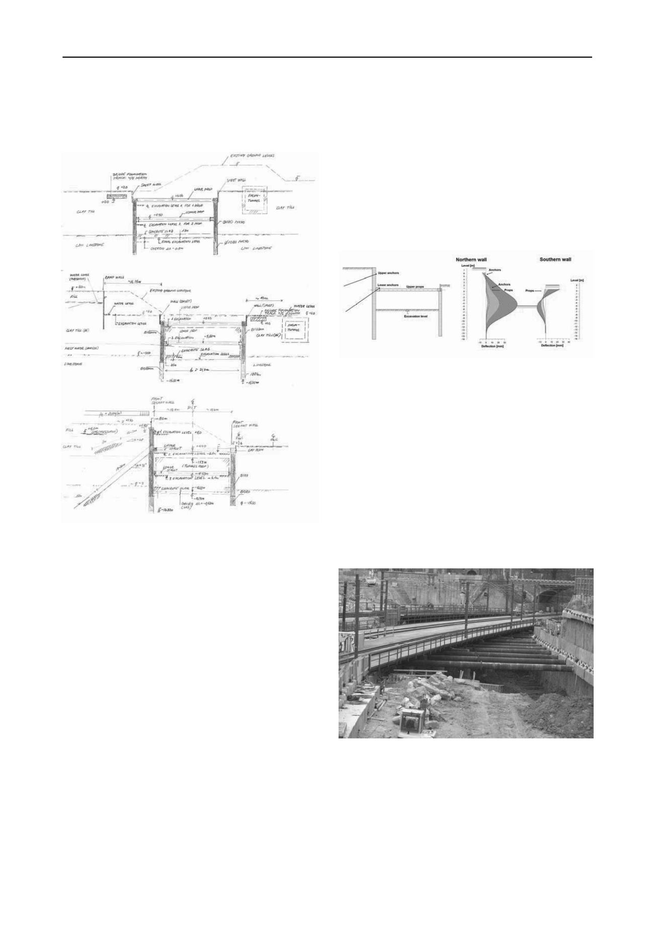
Like for the geological strata, three representative structural
cross sections were developed. The sections appear in Figure
13.
Figure 13. Representative structural cross sections.
The longitudinal reinforcement in the secant piles is
checked to behave elastically in SLS, while in ULS and ALS
plastic behavior is accepted. The shear reinforcement in the
piles are designed using the crack sliding model for a circular
cross sections, which is a further development of the plasticity-
based crack sliding model originally developed for rectangular
beams.
The distribution of sectional forces in props and walings are
like the retaining wall design based on numerical methods, in
this case spring models taking the stiffness of both the soil and
the structural elements into account.
In addition to the load cases considered in the design of the
secant pile walls the support systems are designed to withstand
temperature loads on the props and the two ALS situations;
unintended impacts from a single load and failure of a prop or
anchor.
6 MONITORING
Due to strict requirements for deformations of the railway tracks
and the aim to avoid structural damage to existing structures, a
rather comprehensive monitoring program with accompanying
action lists were developed. The monitoring includes;
monitoring of rotations and deflections of the secant pile walls
via measuring points and inclinometers installed on and in
singled out piles, monitoring of forces in certain struts and
ground anchors and monitoring of movements of foundations,
railway sleepers and terrain in general. Furthermore of course
the ground water heads in both the primary and secondary
aquifers are monitored. All monitoring data are stored in a
database.
The measured deformations and forces are continuously
compared to the expected magnitudes determined in the SLS
analyses. In the analyses a number of combinations of different
ground water and load conditions are investigated, leading to so
called trigger levels for each measuring item in each
construction stage. The trigger levels are threshold values of
when certain actions must be taken or measures must be done.
The trigger levels are presented on a number of drawings, so
that they can easily be compared to the monitored conditions on
site. Figure 14 shows an example of how the trigger levels are
displayed (wall deflections when excavating for establishing of
the lower support system at St. 5200).
Figure 14. Example of trigger level display.
The monitoring is as a starting point performed with
measurements on daily basis, but since most the measurements
are performed automatically the frequency can easily be raised
if any unexpected development in deformations and/or forces is
recorded or lowered if no critical development is recorded.
7 CONCLUSIONS
To be able to construct the future Nordhavnsvej tunnel in
Copenhagen, a construction pit with crossing railway lines and a
tight construction schedule has been established.
Through corporation between Client, contractor and
consultant the mission of not violating short and fixed closures
was accomplished. Figure 15 shows a picture of the project
stage in December 2012, where installation of the lower support
system was ongoing.
Figure 15. Picture of the railway crossing, December 2012.


