2076
Proceedings of the 18
th
International Conference on Soil Mechanics and Geotechnical Engineering, Paris 2013
2 MAIN CONDITIONS
2.1 Geological and geotechnical conditions
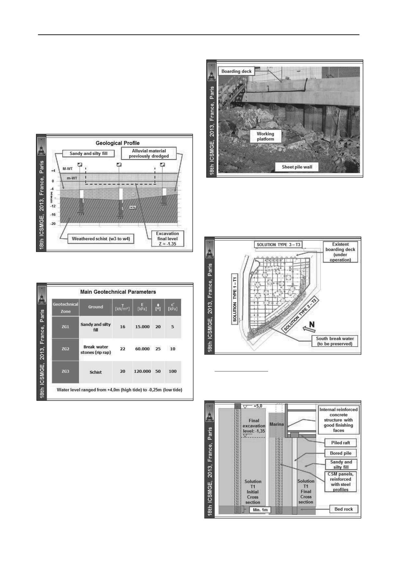
The local geological conditions were homogeneous, but very
complex. The excavation works intersected, from the surface,
level +5,0m, sandy and silty materials, correspondent to the
hydraulic embankment created for working platform purpose.
The embankment fill is resting over the bed rock, weathered
schist, as previously to the construction of the embankment the
existent alluvial material was dredged (Figures 4 and 5).
Figure 4. Geological profile.
The water table level ranged from +4,0m to -0,25m
according to the Atlantic Ocean tide (Figure 5).
Figure 5. Adopted geotechnical parameters.
2.2. Other conditions
The main neighbourhood conditions included the existent
infrastructures, under operation, mainly: the South side break
water, accommodating several infrastructures, and the East side
cruises boarding deck, a reinforced concrete slab supported by
reinforced concrete bored piles. When the embankment was
constructed, a sheet pile wall was installed at the boarding
border face, in order to improve the hydraulic embankment
confinement (Figure 6).
The South side cofferdam walls, as well as of the South side
special foundations had to intersect the break water rip rap (8kN
to 130kN). This situation was confirmed as an important issue
mainly for the execution of the cofferdam walls, as well as for
the construction of the bored piles.
Figure 6. Main neighbourhood conditions: boarding deck.
3 ADOPTED SOLUTIONS
3.1 Global cofferdam
In order to allow the excavation works on dry conditions, three
main retaining structures solutions were adopted (Figure 7).
Figure 7. Adopted solutions for the global cofferdam.
Solution type 1 (T1): soil - cement panels with a cross
section of 2,4 x 0,5m
2
, including 0,20m of overlapping and 1m
of embedment at the bed rock, performed using the CSM
technology (Figures 8 to 11), taking into account the experience
obtained on previous works (Pinto et al., 2011).
Figure 8. Solution T1 – initial and final cross section.


