2072
Proceedings of the 18
th
International Conference on Soil Mechanics and Geotechnical Engineering, Paris 2013
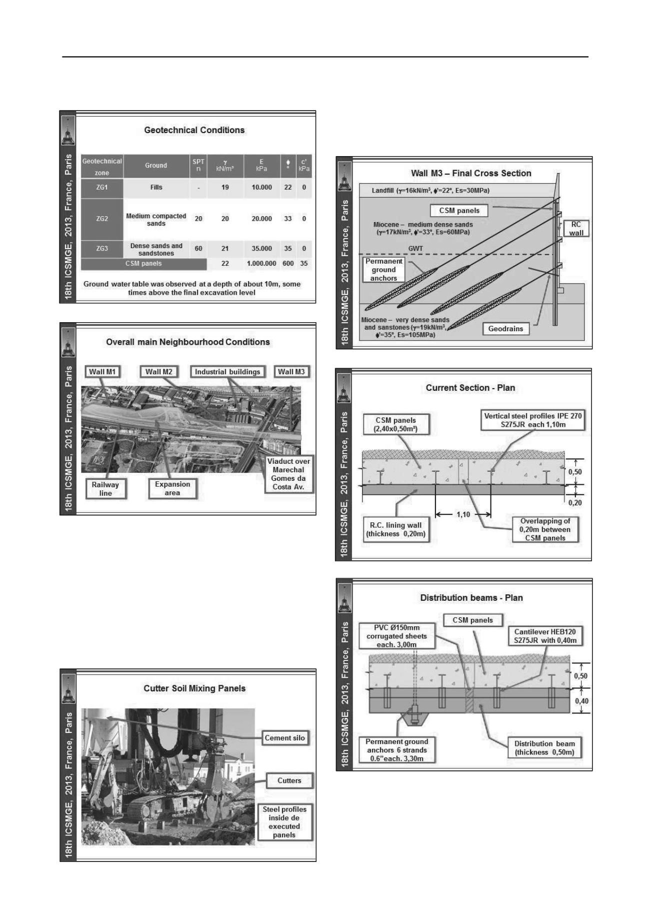
Figure 3. Main geotechnical conditions.
Figure 4. Overall main neighbourhood conditions.
3 ADOPTED SOLUTION
In order to allow the excavation works minimizing the ground
loss of confinement effect, soil - cement panels with a
maximum depth of about 18m and a cross section of 2,4 x
0,5m
2
, including 0,20m of overlapping, were preliminarly built
using the CSM technology. The panels were reinforced with
vertical IPE240 hot rolled steel profiles (Euronorm 19-57),
spaced in average 1,1m, in order to resist to the earth and
ground water pressures, as well as to assure a better control of
the retaining structure deformations (Figure 5).
Figure 5. Execution of the soil - cement panels using CSM technology.
The steel profiles were placed inside the soil - cement
panels, before the cement started the curing process, and were
braced by four or three levels of permanent ground anchors,
applied at the reinforced concrete capping beam, as well as at
the distribution beams (Figures 6, 7 and 8).
Figure 6. Final cross section of the wall M3.
Figure 7. Plan of the wall M3 current section.
Figure 8. Plan of the wall M3 at the distribution beams section.
As already stated, according to the innovative solution
combining the Berlin wall with the CSM technology, the soil -
cement panels were designed in order to be integrated on the
final earth retaining solution, including the 0,2m thickness
lining reinforced concrete (RC) wall and beams (capping and
distribution), and also to minimize the water inflow to the


