2068
Proceedings of the 18
th
International Conference on Soil Mechanics and Geotechnical Engineering, Paris 2013
This present paper focuses solely on the temporary retaining
structures in the railway crossing which the parties - in close
corporation - identified as the optimal.
2 OVERALL GEOMETRY
The vertical alignment of the tunnel is governed by the
alignment of the existing rails which are not allowed to be
changed. This means that the depth of the construction pit is
determined from the height of the future permanent tunnel
structure and a required soil cover between the railway tracks
and the tunnel roof. The width of the construction pit is about
20m
Figure 3 shows a plan and a longitudinal section at the
railway crossing (from St. 5075 to St. 5230).
Figure 3. Plan and longitudinal section at the railway crossing.
As shown in Figure 3 the existing railway lines lies in a dell
in the terrain. This dell is dug out in the glacial deposits when
the railway lines were established.
3 GROUND CONDITIONS
The ground conditions at the railway crossing – and for the
Nordhavnsvej project in general - are characteristic for the
Copenhagen area.
3.1
Soil
Below a thin layer of fill, the intact soil generally consists of a
10-20m thick quaternary layer of firm clay till with
encapsulated layers of melt water sand and gravel. Underneath
the quaternary soils limestone is met where the upper 3m is
assumed to be glacially disturbed.
As shown in Figure 4 the number of geotechnical
investigations in the railway crossing is significant.
Figure 4. Plan of geotechnical investigations.
The soil parameters are determined from shear vane tests and
SPTs carried out in the boreholes, triaxial and oedometer tests
performed in the laboratory on the clay till, VSPs and a priori
knowledge of the soil conditions in general.
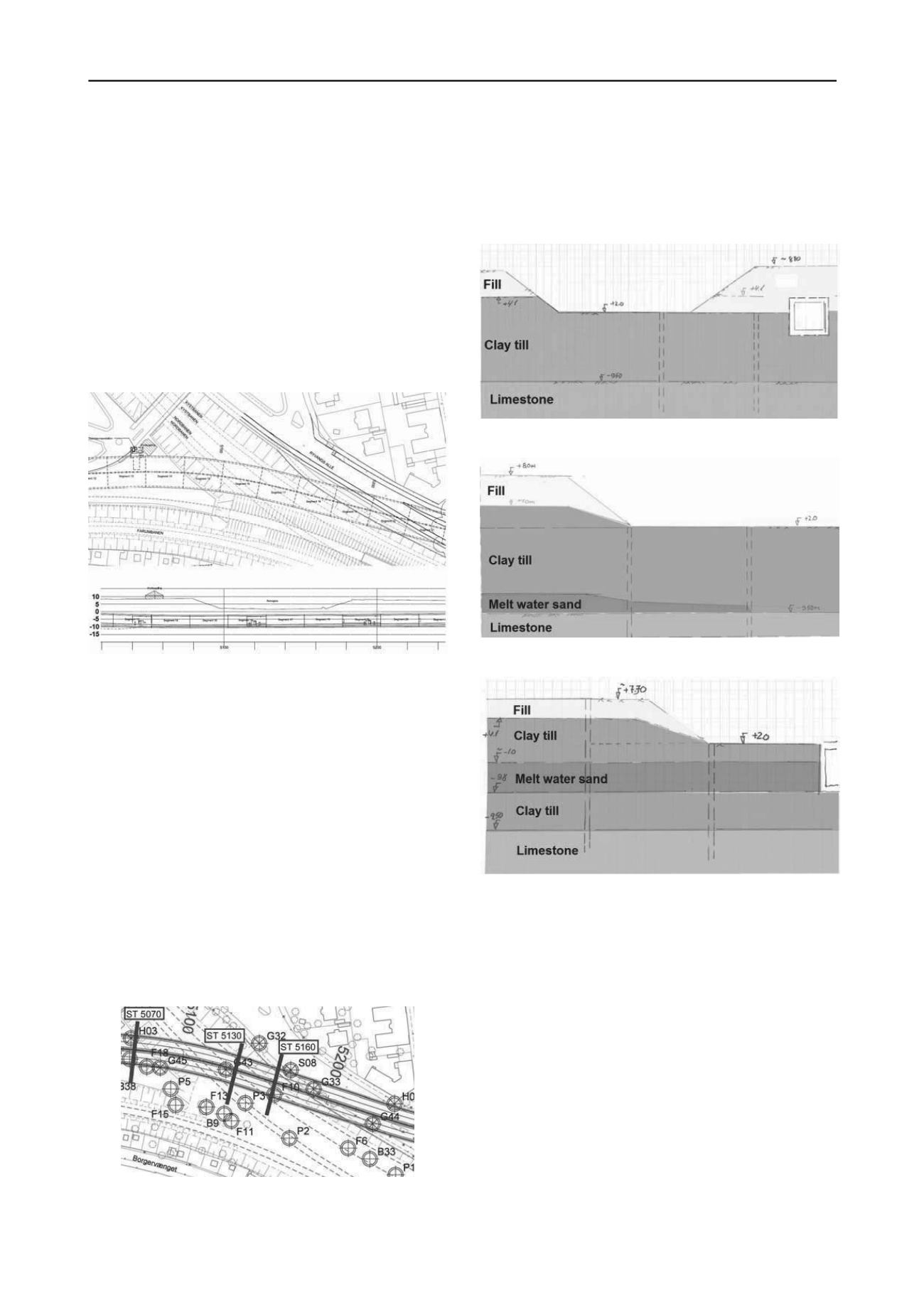
The sections in St. 5075, St. 5130 and St.5160 shown in
Figure 4 indicates the three cross sections being design
profiles/representatives for the railway crossing. Figure 5-6
show the assumed geological strata at these three sections
Figure 5. Geological stratum at St. 5075.
Figure 6. Geological stratum at St. 5130.
Figure 7. Geological stratum at St. 5160.
3.2
Ground water
At Nordhavnsvej the primary and secondary aquifers are
separated. The primary aquifer is the limestone and the
secondary aquifer is in the quaternary soils. The water levels are
more or less coincident situated a few meters below original
glacial ground level except at the railway crossing where the
dell in the ground level causes the ground water level down to
the terrain.
For the construction of the Nordhavnsvej tunnel it is
necessary to lower the ground water level in the limestone
temporarily to be able to build the permanent structures. Due to
limitations on the allowance of lowering the ground water level
in the secondary aquifer, a significant lowering and re-
infiltration management system was established.
4 STRUCTURAL SOLUTION
Because of the requirement, that all four crossing railway lines
must be in service in the complete construction period except
for a few short closures, a number of different solutions to


