2069
Technical Committee 207 /
Comité technique 207
respect that were considered during the early stages of the
project, including pipe arching, top down and the chosen
solution, being construction of four temporary steel bridges
carrying each a railway line across an open construction pit,
facilitating the tunnel to be build bottom up.
Since the railway lines cross the construction pit with rather
small angles, the bridge spans are between approx. 40m and
70m. The bridges are prefabricated steel bridges founded on 2-5
bored piles below each bridge placed inside the pit, the retaining
walls and concrete foundations with transition slabs at each end.
For safety reasons the bridges are connected in pairs to
provide footpaths. Figure 8 shows a cross section in the bridges.
Figure 8. Cross section in temporary bridges.
The type of retaining wall is determined by the
constructability in the very hard clay till and the limestone,
containing significant amounts of boulders and flint
respectively.
In the tender material a solution with steel sheet piles placed
in a cement-bentonit slurry trench was prescribed, but during
the optimization phase the contractor suggested to use secant
pile walls, type hard-firm, since this method is already used
outside the railway crossing and consequently well tested before
constructing the retaining walls during the railway closure.
The secant piles are established with the Kelly method, cased
until 0.5m below excavation level (diameter 1180mm) and
below that uncased to the bottom (diameter 1080mm). The
walls are staggered so that the firm piles are stopped 1.5m
below excavation level. Hard piles are reinforced with 14 or
18pcs. K40 longitudinal reinforcement and K14 spiral shear
reinforcement.
To avoid significant crushing works on the secant piles after
establishing the tunnel, HEB profiles are casted into the top of
the reinforced secant piles or the capping beam and timber
lagging is used as infill, forming fixed soldier pile walls, which
can easily be cut down and removed respectively. Figure 9
shows one of the encastered soldier pile walls.
Figure 9. Encastered soldier pile wall.
The support system in the railway crossing consist of two
levels of walings and steel tube props, supplemented by ground
anchors to balance the system where the ground level is
significantly different on the two sides of the construction pit.
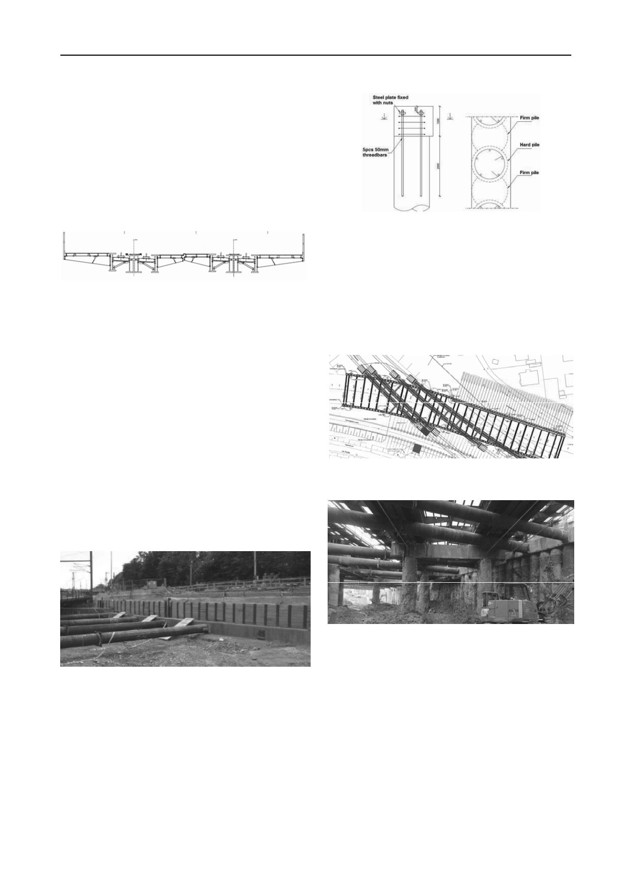
Where the terrain is at railway level, the upper waling is a
concrete capping beam placed on top of the secant piles and
attached to the piles by 5 threadbars per reinforced pile as
shown in Figure 10. The solution is chosen because it is fast to
wash away the upper (poor) concrete in the secant piles, place
the prefabricated reinforcement cages for the capping beam and
get it all casted together.
Figure 10. Connection between reinforced secant piles and upper
capping beam.
The props in the upper support system are all steel types with
25mm thickness and diameters ranging from 610mm to 820mm
and placed unevenly with distances of about 6-8m. The location
of the props are of course governed by the capacities of the
capping beams and props, but also by the location of the
concrete beams spanning from the capping beam to the
foundation piles supporting the rail bridges. Figure 11 shows
the upper support system and support beams for the bridges and
Figure 12 shows a picture of one of the support beams.
Figure 11. Upper support system and support beams.
Figure 12. Picture of support beam.
The props and walings in the lower support system are very
temporary. As soon as the bottom slab of the tunnel is
established, the props and walings are removed. Consequently a
steel solution with double HEB-profiles and steel tube props is
chosen, since the establishing and removing of this system is
less time consuming than any concrete solution.
5 DESIGN
The design of the retaining walls and the support systems have
been carried out using 2D numerical approaches since the effect
of asymmetric loading is considerable; different terrain levels,
different ground water levels and different loads on each side of
the construction pit leading to props pushing excess force from
one side to the other. For ULS analyses FEM have been used
and cross checked with subgrade reaction models. In SLS small
strain stiffness has been considered in FEM analyses.
To ensure that any 3D effects – like the partial loads from
trains - were considered realistically in the 2D models, small 3D


