2077
Technical Committee 207 /
Comité technique 207
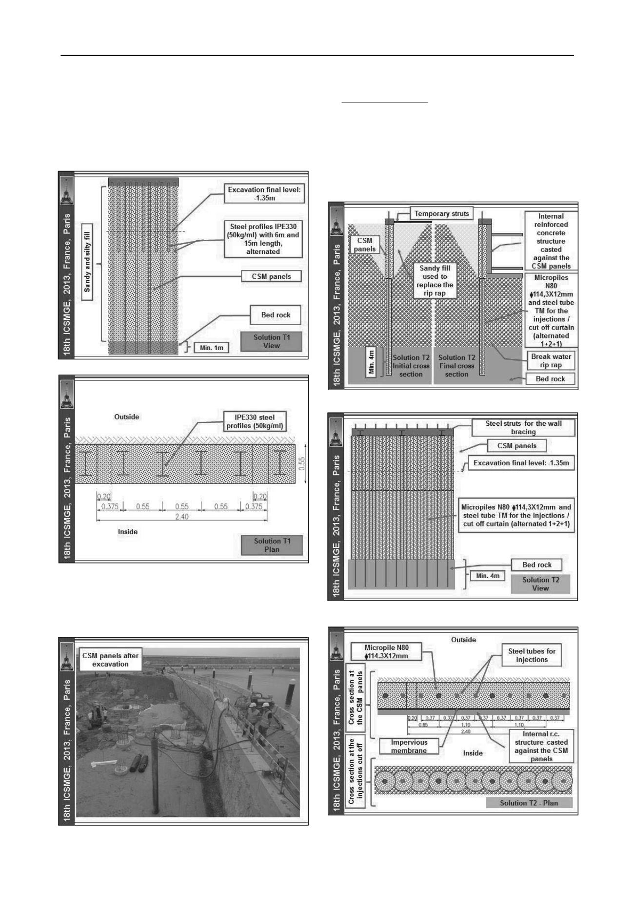
The soil - cement panels, with UCS resistance not lesser
than 4MPa, were reinforced with vertical IPE330 steel profiles
(Euronorm 19-57), spaced 0,55m in average, in order to resist to
the earth and water pressures, as well as to ensure a better
control of the deformations. The steel profiles were placed
inside the panels, before the cement started the curing process
and capped by a reinforced concrete beam (Figure 8 to 11).
Figure 9. Solution T1 – view.
Figure 10. Solution T1 – plan.
The soil - cement panels will be demolished from the
internal structure foundation level to the top, in order to allow
the reinforced concrete (r.c.) wall with a very good finishing
face, being visible from the adjacent marina, (Figure 12).
Figure 11. Solution T1 – view of soil-cement panels after excavation.
Solution type 2 (T2): soil - cement panels with a cross
section of 2,4 x 0,5m
2
, including 0,20m of overlapping on a
height of approximately 6.5m, correspondent to the previous
excavation depth, performed in order to replace the break water
rip rap by a sandy fill. The panels were built using the CSM
technology. Bellow the soil - cement panels the cofferdam cut
off effect was assured through a curtain, performed using
alternated slurry cement injections through steel tubes and
micropiles N80
114,3x12mm, those also with foundation
purposes and sealed 4m on the bed rock (Figures 12 to 15).
Figure 12. Solution T2 – initial and final cross section.
Figure 13. Solution T2 – view.
Figure 14. Solution T2 – plan.


