2052
Proceedings of the 18
th
International Conference on Soil Mechanics and Geotechnical Engineering, Paris 2013
methods, and actual performance at construction sites where the
design methods were implemented are described below.
3 CENTRIFUGE MODEL EXPERIMENT OF INCLINED-
BRACELESS RETAINING WALL
3.1
Experiment method
GL -11.9m
GL
±
0m
Step 0(Before excavation)
Step 1(Excavationto -3.3m)
Step 2(Excavationto -5.3m)
Step 3(Excavationto -9.6m)
Retainingwall
Inclinationof 10deg.
0
2
4
6
8
0
10
20
30
Measurement position (m)
Horizontal displacement of retaining wall (cm)
Vertical, Excavation of 3.3 m depth
Vertical, Excavation of 5.3 m depth
Vertical, Excavation of 9.6 m depth
10deg.inclination, excavation of 3.3 m depth
10deg.inclination, excavation of 5.3 m depth
10deg.inclination, excavation of 9.6 m depth
0
10
20
30
0
5
10
15
Horizontal displacement at top
retaining wall
Excavation depth (m)
Vertical
10deg.inclination
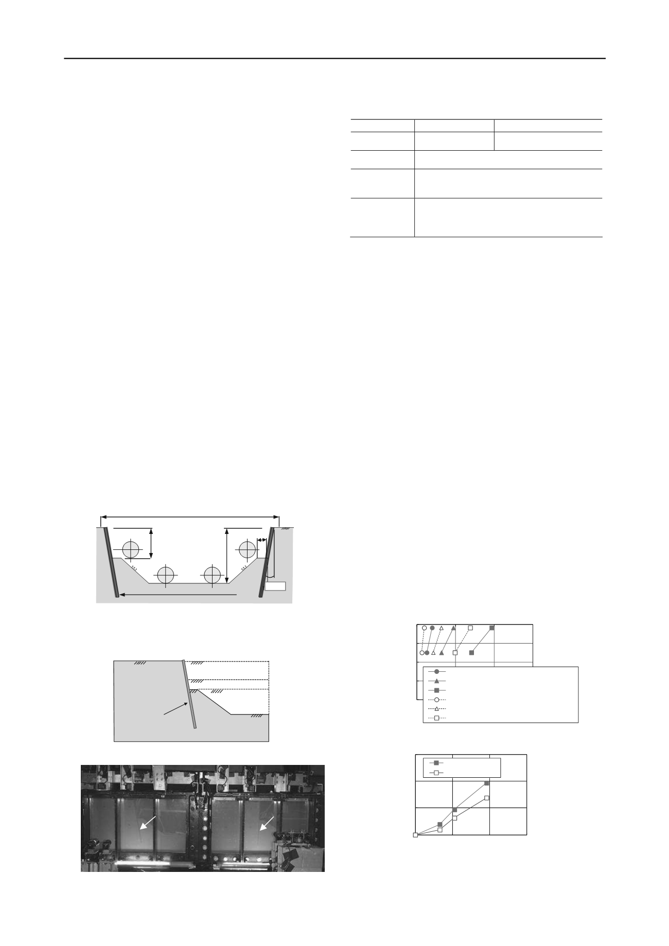
A 1/33-scale model ground was prepared to develop excavation
cross sections of applicable construction sites (Figure 3) for this
experiment. A maximum centrifugal acceleration of 33
g
was
loaded to examine deformation of the retaining wall and
distribution of the earth pressure. Figure 4 shows an outline of
the model ground. The dimensions of the soil container were 80
cm width × 50 cm height × 20 cm depth. The front side of the
container was fabricated from an acrylic plate so that ground
displacements could be measured. A Teflon sheet was attached
between the soil container, including the acrylic plate, and the
model ground to reduce friction. The depth of the model ground
was developed with berm to a maximum of 29 cm, and the
height of the retaining wall was 36 cm. The model ground is
shown in Photo 1. The retaining wall was created assuming that
the retaining walls would be made of steel sheet piles. A
compact earth pressure gauge (6 mm dia., capacity of 1 MN/m
2
)
was embedded at seven locations on the active side and at four
locations on the passive side to measure the earth pressure
acting on the wall surface. The retaining wall model was
installed and then filled with dry Toyoura standard sand by the
airdrop method to prepare the model ground. Excavation steps
were simulated during the experiment by repeating the method
of loading centrifugal acceleration after the prescribed
excavation work was performed at a 1
g
site. Table 1 shows the
experimental cases.
Figure 3. Cross-section of inclined-braceless retaining wall applied at
site
Figure 4. Outline of model ground.
Photo 1. Model ground
Table 1: Experiment Cases
No.
Case 1
Case 2
Retaining wall
conditions
Vertical
Inclined
(inclination of 10 degree)
Retaining wall
model
Made of aluminum, thickness of 7 mm
Ground
Material: Toyoura standard sand (dry)
Density: ρ
d
=1.55 g/cm
3
Preparation method: Airdrop method
Excavation
steps
Step 0: Before excavation
Step 1: Excavation depth of 3.3 m
Step 2: Excavation depth of 5.3 m
Step 3: Excavation depth of 9.6 m
3.2
Experiment results
Figures 5 and 6 show the deformation behavior of the retaining
wall due to excavation work. The displacements shown below
were converted to actual-scale displacements by multiplying the
experimental measurement results by 33. Figure 5 shows the
displacement distribution of the retaining wall for each
excavation stage. The horizontal displacement was larger at
higher sections of the wall, and deformation occurred in the
frontal incline with the lower section of the wall as the axis.
Regardless of the excavation depth, the amount of horizontal
displacement of the inclined walls was smaller than that of the
vertically installed walls. Figure 6 shows the relationship
between the excavation depth and horizontal displacement at
top of the wall. The deformation increased in correlation to the
depth; the displacement of the vertically installed wall was
measured at the maximum excavation depth as 20 cm, whereas
that of the inclined wall was about 14 cm. Thus, the
experimental results confirmed that the amount of deformation
was about 30% smaller with inclined walls.
Strain gauges were attached to the front and back surfaces of
the wall in the direction of the depth at three locations in order
to obtain the bending status of the wall. Figure 7 shows the
depth distribution of the bending strain: the maximum value
was obtained in the vicinity of the center of the wall regardless
of whether the wall was inclined. The maximum bending strain
was smaller with inclined walls than with vertically installed
walls regardless of the excavation depth. The gap between the
two was larger when the excavation depth was 9.6 m than when
it was 3.3 m; the effects of inclining the wall were significant
and evident.
Constructionwork zone(W= 30m)
Inclined steel sheet pile type SP-IV
L = 12 m
5.3m
9.6m
1.6m
10deg.
Figure 5. Horizontal displacement distribution of retaining walls
Retaining wall
(inclination of 10deg.)
Retaining wall
(vertical installation)
Figure 6. Relationship between excavation depth and horizontal
displacement of retaining walls


