2048
Proceedings of the 18
th
International Conference on Soil Mechanics and Geotechnical Engineering, Paris 2013
constructed by mixed in place columns (MIP), which rest on
supporting walls (also mixed in place columns) oriented in the
direction of the slope. The earth pressure exerted from the slope
was transferred to 5 meter deep mixed in place walls underneath
the planed building at the base of the slope. Figure 1 shows the
slope with the supporting structure and Figure 2 a detail of the
MIP columns.
Figure 1. Overview of slope and support structure including critical
building.
Figure 2. Layout of support structure (MIP columns).
Based on the results from site investigations a representative
underground model consisting of three layers was established
for the 3D finite element analysis, namely soft sandy silt (0-4 m
below surface), stiff laminated sand-silt (4-8 m below surface)
and semi-solid sand-silt (below 8 m from surface). The most
important parameters for these layers are summarized in Table
1. E
oed
ref
is the stiffness from an oedometer test for the reference
vertical effective stress of 100 kPa, E
50
ref
is a secant stiffness at
50% of maximum deviatoric stress in a triaxial compression test
at a reference cell pressure
3
' = 100 kPa, E
ur
ref
is the
unloading/reloading stiffness, again at a reference cell pressure
of 100 kPa from a triaxial test, and m is a parameter
determining the stress dependency of above stiffness
parameters.
', c' and
are the conventional Mohr-Coulomb
strength parameters which define ultimate strength in the
Hardening Soil model.
The MIP-method improves the mechanical properties of a
soil by mechanically mixing and adding binder slurry. The
result is a “soil-concrete-mixture” in which the soil is used as
aggregate. For the MIP-columns a constitutive model based on
the Mohr-Coulomb failure criterion was applied. Based on an
unconfined compressive strength of 5 MN/m², whereas this
value includes a partial factor of safety on material strength, the
material parameters listed in Table 2 have been adopted.
Table 1. Material parameters for Hardening Soil model for soil layers.
Table 2. Material parameters for MIP-columns.
Parameter
MIP
Friction angle,
' (°)
30
Cohesion, c' (kPa)
250
Unit weight,
(kN/m
3
)
22
Elasticity modulus (kPa)
300000
Tension cut off,*
t
(kPa)
125
* based on reinforcement by steel rods and nails
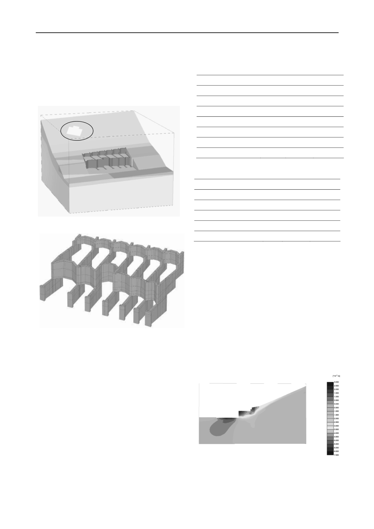
The results of the calculation show the expected stiff behaviour
of the chosen support system. The maximum calculated
horizontal deformation of about 15 mm occurs at the front upper
corner of the lower excavation step (Figure 3). At the back of
the wall (near the border of the neighbouring property)
deformations are in the order of millimetres and thus the
expected settlements in this area can be considered to be not
significant and will not cause any damage to the building
(Figure 4). However, the finite element analysis could not
model the construction process of the MIP-columns, i.e. the
columns were assumed "wished-in-place" before excavation
starts and therefore displacements due to the construction
process have to be added to these values.
The 3D-model was also used to check the tension zones in
the MIP-body. The main tension stresses were located at the
connections of the arches and the wall elements. In this area the
MIP-wall was reinforced with steel beams (HE-B profiles).
Figure 3. Calculated horizontal displacements, cross section
The measurements during construction on one hand confirmed
the results for the numerical analysis but on the other hand
showed that significant deformations occurred during
construction of the MIP-columns itself (Figure 5). After
construction of the columns (panels) deformation measured
were less than 15 mm, comparing well with the finite element
Parameter
Layer 1
Layer 2
Layer 3
Friction angle,
' (°)
25
27.5
30
Cohesion, c' (kPa)
0
1
5
Dilatancy angle,
(°)
0
0
0
Unit weight,
(kN/m
3
)
20
20.5
21
E
oed
ref
= E
50
ref
(kPa)
10000
25000
45000
E
ur
ref
(kPa)
30000
75000
135000
m (-)
0.5
0.5
0.5


