2049
Technical Committee 207 /
Comité technique 207
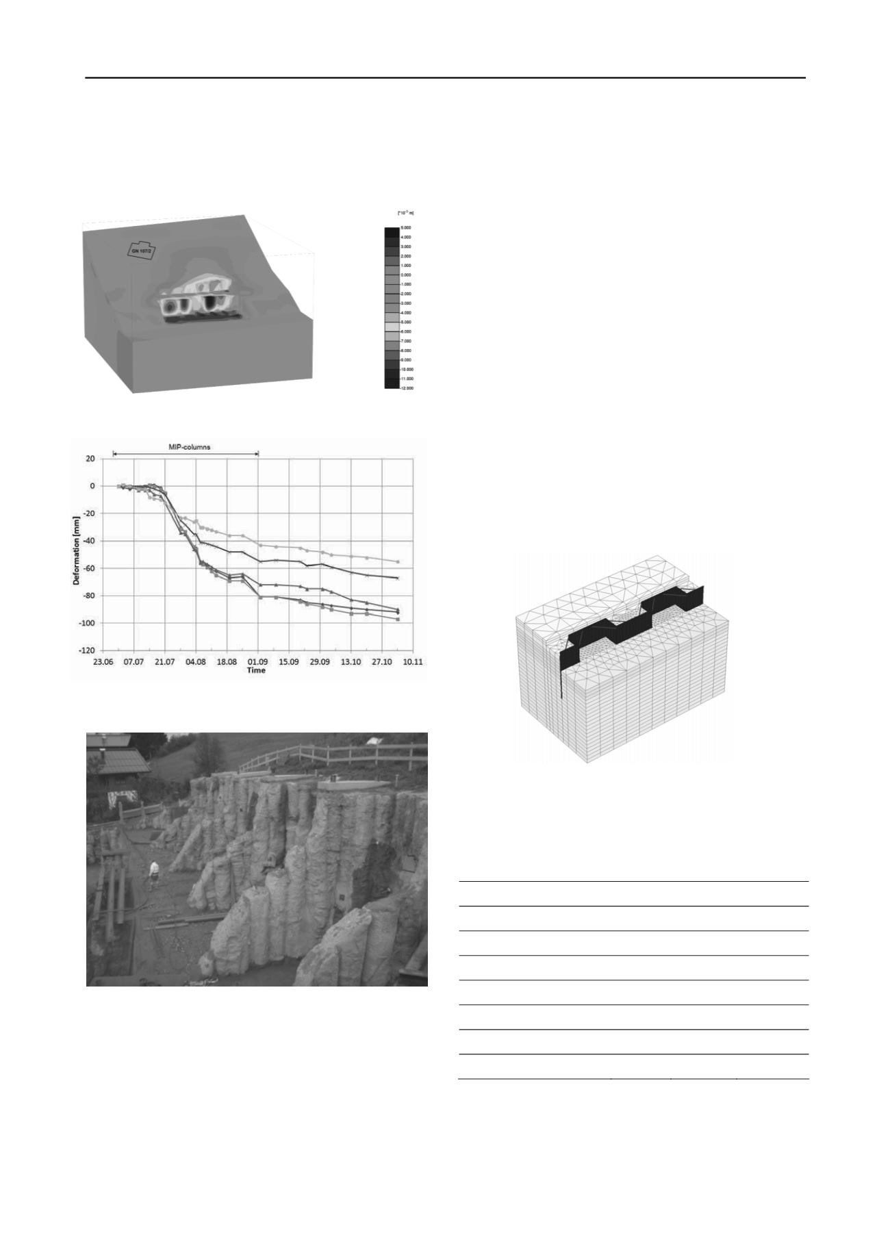
predictions. Figure 5 shows the deformations of different points
on the top of the MIP-wall. At the neighbouring buildings no
movements were recorded. Figure 6 presents a view of
excavated MIP-walls.
Figure 4. Calculated horizontal displacements with critical building
Figure 5. Measured horizontal displacements at several points at the top
of the MIP-wall
Figure 6. View of excavated MIP-walls
The large deformations during the production of the columns
had two main reasons. In the first part of the production too
many MIP columns were produced within a small area. The
MIP columns, which take some time to gain strength, weakened
the slope during construction, which was already close to
critical state. Furthermore, to reduce the length of the MIP
columns (in order to save money), deeper working planes than
planned were excavated.
This presented case study clearly shows that it is possible to
support the earth pressure exerted from a slope by arches
constructed by means of soil improvement techniques without
any anchors reaching on neighbouring ground. The numerical
analysis was able to prove that the design concept is feasible,
however, it is important to observe the deformation during the
construction stages because not all aspects of the construction
process, in this case of the MIP-columns, can be taken into
account in the numerical model.
4 EXAMPLE 2 - SERRATED SHEET PILE WALL
The second example is concerned with the same problem,
namely limited space for support measures, but this time it is in
an urban environment, namely in the city of Salzburg, Austria.
Again the excavation was very close to the adjacent property
and it was not allowed to put any construction elements, such as
ground anchors, there. In this case the solution chosen was a
serrated sheet pile wall. Generally, the subsoil conditions in
Salzburg consist of a top layer with backfill and gravel, and soft
silty sand and clayey silt layers underneath. The layout of the
sheet pile wall follows from Figure 7 (3D finite element model).
Every 6 to 8 m there is a 3 m deep indentation in the sheet pile
wall. The construction of diagonal compression and tension bars
at the top transfers the earth pressure to the right-angled parts of
the sheet pile walls. A steel construction, similar to a whaler
beam, on top prevents non-homogeneous deformations of the
wall. After excavation a drainage layer and a concrete slab is
installed to prevent long term movements of the wall and to
reduce the influence of the soft layers below excavation level.
Figure 7. 3D finite element model
The key material parameters for the soil layers considered in the
analysis are listed in Table 3. Again the Hardening Soil model
has been employed.
Table 3. Material parameters for Hardening Soil model for soil layers.
Parameter
backfill
silty sand
clayey silt
Friction angle,
' (°)
35
27.5
25
Cohesion, c' (kPa)
0,1
3
5
Dilatancy angle,
(°)
0
0
0
Unit weight, (kN/m
3
)
19/21
20/21
18/20
E
oed
ref
= E
50
ref
(kPa)
52000
30000
15000
E
ur
ref
(kPa)
208000
120000
60000
m (-)
0
0.5
0.5
The 3D model showed that deformations can be kept to a
minimum with maximum values below 10 mm (Figure 8),
which was also confirmed by observations during construction.
Deformations due to driving and removing of the sheet pile wall
are not considered in the analysis. Experience has shown that in
this type of soils settlements can reach 20 to 30 mm, and in this
particular case observed values were within the lower range.


