2050
Proceedings of the 18
th
International Conference on Soil Mechanics and Geotechnical Engineering, Paris 2013
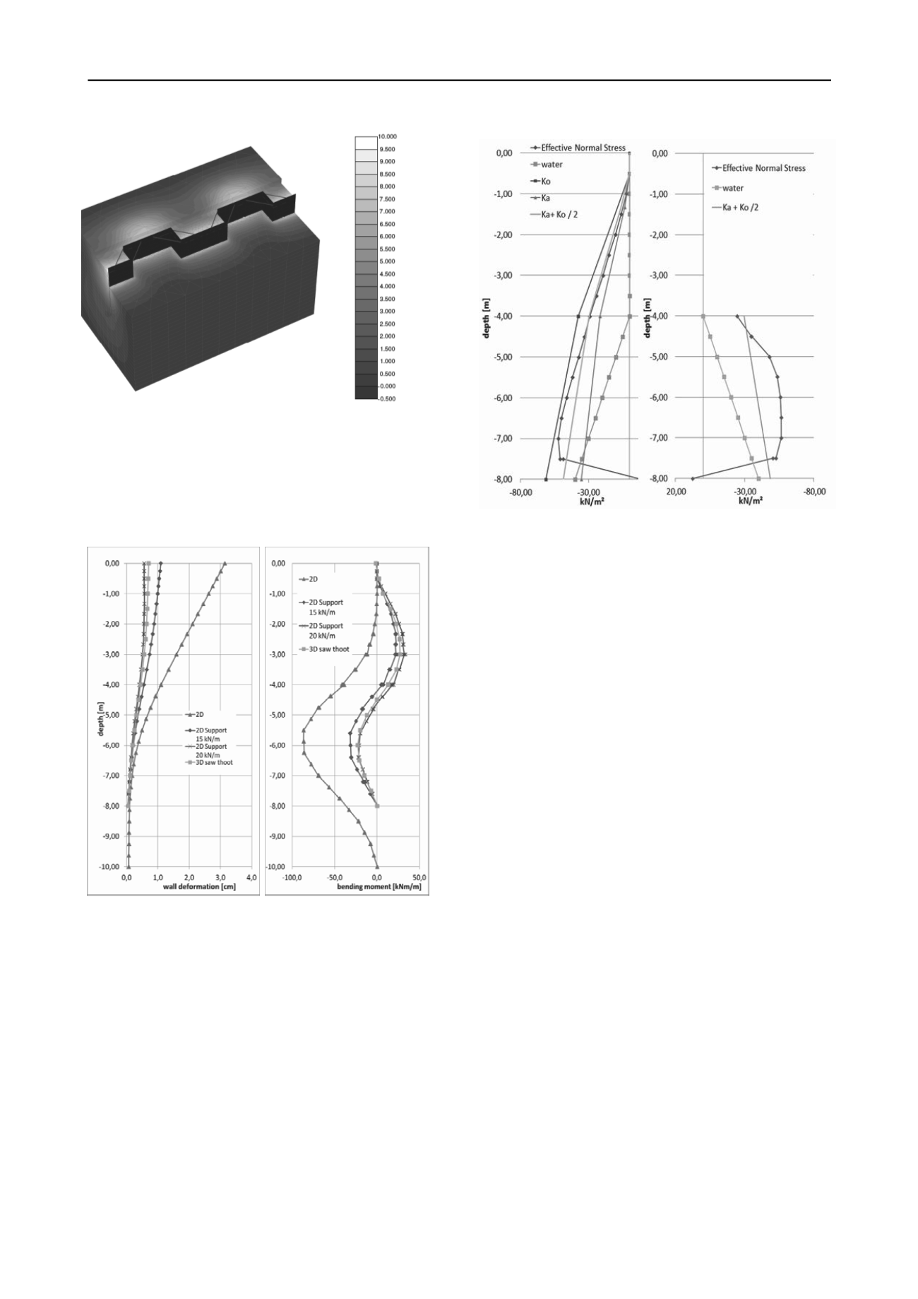
Figure 8. Calculated horizontal displacements
The bending moments of a sheet pile wall with this particular
shape and the strengthening construction on top of the wall is
not the same as for a cantilever wall, which one would obtain
from a 2D analysis and therefore the 3D analysis was essential
and helped to estimate the influence of the special support
measures. However, 3D finite element analyses are quite time
consuming if many different scenarios have to be investigated.
Figure 10. Earth pressure distribution on active and passive side
For the given geometry (distance of 8 m between the
rectangular walls) this earth preasure distribution leads to a
maximum resistance by wall friction of about about 20 kN/m.
This shows a good correlation with the presented calculations.
5 CONCLUSIONS
3D finite element modelling allows complex geotechnical
structures to be analysed. In the two presented case histories the
calculations helped to estimate the arching effect of a curved
retaining structure in order to design an excavation pit without
any anchors reaching on the neighbouring ground. In the second
example the behaviour of a serrated sheet pile has been
investigated. In both case the numerical analyses proved the
feasibility of the chosen design and improved the understanding
how these complex structures behave.
However, even with 3D models it is usually not possible to
include all excavation stages in great detail and, more
importantly, installation effects are beyond the capabilities of
standard numerical tools and this has to be kept in mind when
assessing numerical results. Therefore it is essential to monitor
the behaviour of the structure during construction and have
appropriate counter measures in mind when deformations due to
installation effects or unforeseen ground conditions reach
critical limits.
Figure 9. Comparison of 2D and 3D analysis of wall deformation and
bending moments
An attempt was therefore made to develop an equivalent 2D
analysis for performing parametric studies for a preliminary
design. For that reason a 2D model of the sheet pile wall with a
supporting force on top of the wall was created. It turned out
that for the case of a 8 m deep sheet pile wall and a 4 m deep
excavation (groundwater is also at 4 m depth) a supporting force
between 15 kN/m und 20 kN/m lead to similar wall
deformations und bending moments (Figure 9). This supporting
force has to be carried from the additional wall elements
spanning across the edges of the two lines of the serrated sheet
pile wall (see also Figure 8). The calculations revealed that the
earth pressure distribution of the rectangular part of the serrated
sheet pile wall is between the active and the at-rest earth
pressure (see Figure 10).
6 REFERENCES
Brinkgreve R.B.J. and Swolfs W.M. 2007. Plaxis 3D Foundation,
Users Manual, Plaxis bv, Delft, The Netherlands
Schanz T., Vermeer P.A. and Bonnier P. 1999. The Hardening-Soil
model: Formulation and verification.
Beyond 2000 in
Computational Geotechnics
, R.J.B. Brinkgreve (ed.), Balkema,
Rotterdam, 281-290.


