1740
Proceedings of the 18
th
International Conference on Soil Mechanics and Geotechnical Engineering, Paris 2013
For each of the cutting tools the cutting distance
s
c
in km de-
scribing the tool life was calculated. Given the track radius
r
t
of
the tool in mm or rather the cutting distance of the tool per cut-
ter head revolution 2
π ⋅
r
t
, the penetration rate
p
in mm/rev and
the advance chainage
b
a
and
b
s
of the TBM in m, where the cut-
ting tool was assembled on and disassembled from the cutter
head, the cutting distance
s
c
in km can be approximated by (1).
= 2 ∙
1000 ∙
−
1
Following that, distinct values for the relevant influencing
factors on the tool life were attributed to each tool change.
Based on the work of T
HURO
(2002) in general geotechnical pa-
rameters and TBM design and advance parameters were consid-
ered as influencing factors.
The attribution of distinct values for geotechnical parameters
required the formation of geotechnical sections. The criteria ap-
plied for the formation of the sections were:
•
Constant share of different soil types in the excavation face
in % (+/- 10%).
•
Constant thickness of the cover above the tunnel axis
h
ta
in
m (+/- 10 m).
•
Constant water table above the tunnel axis
h
wt
in m
(+/-5 m).
The documentation of the tool changes in the reference pro-
jects is insufficient for a clear determination of the condition of
each tool at the boundary between geotechnical sections. The at-
tribution of distinct values for geotechnical parameters is there-
fore limited to tools that were assembled and disassembled on
the cutter head within one section.
The TBM advance data were taken from the data acquisition
system of the TBMs. For each tool change average values be-
tween the chainage of the assembly
b
a
and disassembly
b
s
of the
tool on the cutter head were calculated.
In order to focus the data analysis on the constant wear of the
cutting tools caused by the abrasivity of the excavated soil all
preventive tool changes as well as damages of tools were elimi-
nated from the data pool, because they usually occur before the
wear limit of the cutting tool is reached.
Considering the formation of geotechnical sections and elim-
ination of preventive tool changes and damages, only 23% of all
tool changes could be identified as significant for the constant
tool wear caused by the abrasivity of the soil. The tool changes
utilized in the data analysis are summarized in tab.2.
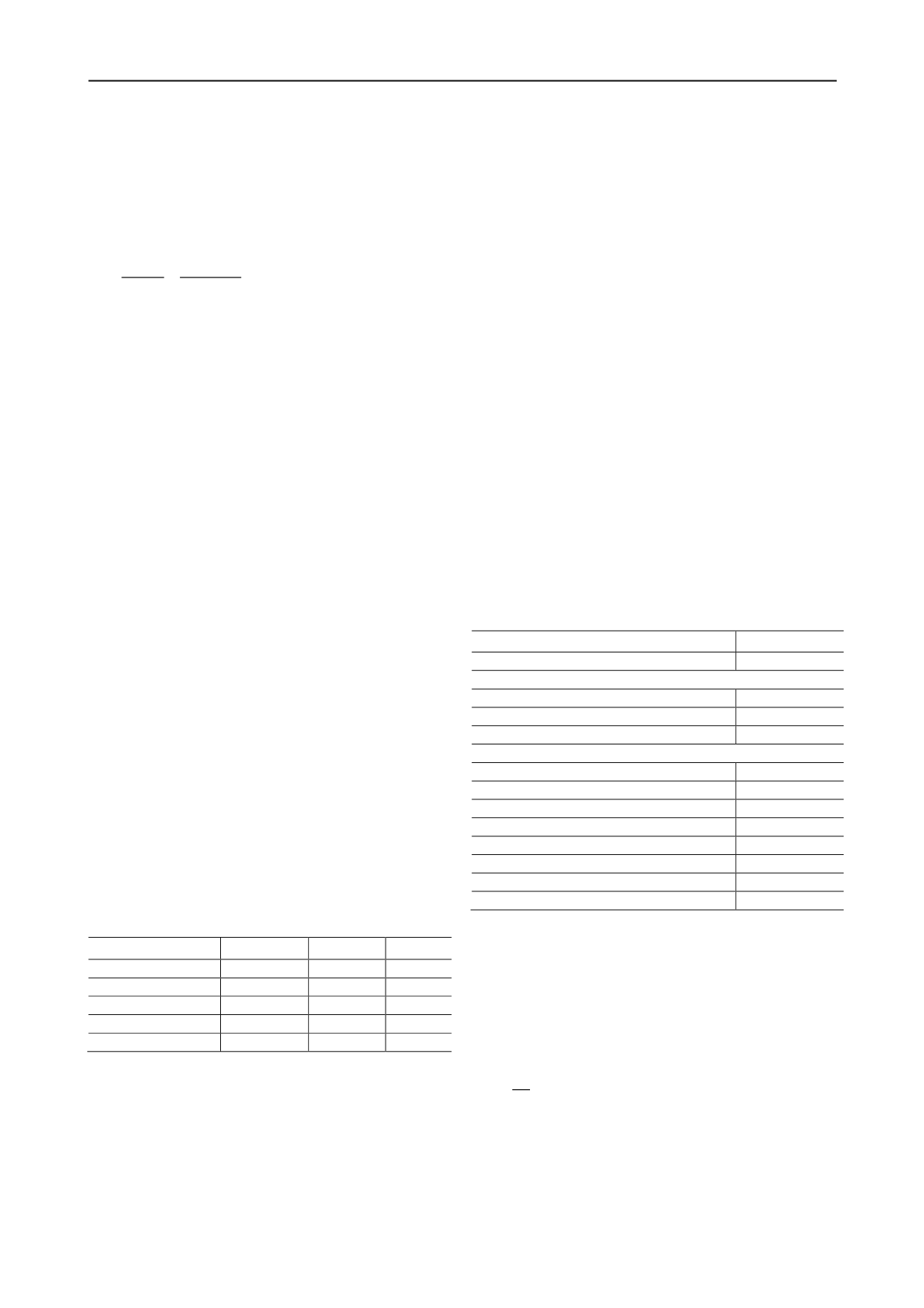
Table 2. Overview of the tool change data utilized for the data anal-
ysis.
Soil type
Volume
Disc cutters
Scrapers
DIN EN 14688 T1
[m³]
[pcs.]
[pcs.]
Clay & Silt
2.787.514
32
119
Sand
620.783
125
106
Gravel
817.076
278
245
Total:
4.225.373
435
470
2.2
Analysis method
The process oriented empirical analysis of the tool change data
has the target to identify and quantify the relevant influencing
factors on tool life. In addition, the following factors given in
the reference projects were considered in the analysis method:
•
Variance of the documentation quality.
•
Range of different data types to be analyzed.
•
Unclear definition of statistical properties for the basic data.
Due to these factors e.g. a multivariate analysis of variance for
relevant influencing factors is not feasible. Consequently op-
tions for the standardization of a variety of the impact factors
were developed, in order to enable a selective regression analy-
sis of single factors or combinations of factors. The available
options are based on comparison of different advance situations:
•
Comparison of the cutting distance
s
c
in different geotech-
nical sections excavated by a TBM without changing TBM
design and advance parameters.
•
Comparison of the cutting distance
s
c
for different TBM de-
sign parameters in a geotechnical section without changing
TBM advance parameters.
•
Comparison of the cutting distance
s
c
for different TBM ad-
vance parameters between parallel tunnels excavated by
identical TBMs.
•
Comparisons of the cutting distance s
c
for individual impact
factors between different projects, in case all other impact
factors can be standardized.
2.3
Results
In the first step the data analysis enables the qualification of the
influencing factors on tool life in the TBM design and advance
parameters given in tab. 3. However, the impact of these factors
could not be quantified based on the available data, mainly due
to very limited fluctuation range of the factors in the reference
projects.
Table 3. Overview of the influencing factors qualified in the data
analysis and the according fluctuation range in the reference projects.
TBM design parameters:
Range:
Cutter head opening ratio OR
TBM
[%]
28,4 – 31,0 %
Disc cutters:
Diameter [inch]
17”
Hardness of the cutter rings [HRC]
57 +/-1
Height above cutter head steel structure
h
dc
[mm]
175 mm
Scrapers:
Width
t
sc
[mm]:
100 mm
Wear protection of the cutting edge:
Tungsten carbide
Tungsten carb. coverage of the tool surface [%]:
30 - 85%
Height above cutter head steel structure
h
sc
[mm]
140 mm
TBM advance parameters:
Range:
Cutter head rotation speed
rpm
[1/min]
0,9 – 2,2 1/min
Density of the bentonite suspension
ρ
SF
[g/cm³]
1,15 – 1,37 g/cm³
Support pressure
P
SF
[bar]
0,9 – 3,7 bar
Exceptions to tab. 3 are given by the following three influ-
encing factors that could be quantified in the data analysis.
For disc cutters the impact of the tip width
t
dc
[mm] of the
cutter ring can be quantified. The actual cutting distance
s
c
in-
creases proportionately with the tip width
t
dc
. Based on the most
common value of 19 mm for
t
dc
in the reference projects, the
according impact factor
f
t
on the cutting distance
s
c
for the
prognosis model is described by:
=
19
2
For scrapers the analysis allows for the quantification of the in-
fluence of the penetration rate
p
[mm/rev] and the number of
identical scrapers per cutting track and direction of cutter head
rotation
k
sc
.
The penetration rate
p
influences on the cutting forces
(B
ERETITSCH
1992), thereby increasing penetration rate results
in increasing cutting forces and wear. Based on the average val-


