1744
Proceedings of the 18
th
International Conference on Soil Mechanics and Geotechnical Engineering, Paris 2013
2 COMPENSATION GROUTING FOR SHALLOW
FOUNDATIONS
Compensation grouting is frequently applied in urban tunnelling
projects to reduce the impact of tunnelling to adjacent buildings
providing the advantages of an active protection measure
according to the observational method. For a detailed
description of the compensation grouting method see Falk and
Kummerer (2012). In the particular case of Metro B1,
compensation grouting substituted the original design with full
face (jet) grouting of the cross section for the following reasons:
reduction of space requirements as all activities were
located within small shafts and one site installation area
no additional area needed to provide the space for drilling
rigs (e.g. on roads closed for traffic)
simple drilling geometry with two parallel grouting pipe
(TAM) arrays avoiding complex 3D drilling set-ups
reduction of spoil resulting from jet grouting
real-time monitoring of critical buildings with the
possibility of actively correct undue deformations.
Before implementing compensation grouting for 8 critical
buildings close to ‘Bologna station’, the actual state and
tolerable deformations of these structures were assessed in
comprehensive studies. The allowable maximum absolute and
differential settlement was defined with 15 mm and 1/500,
respectively. Deformation analyses based on the well-known
soil behaviour showed that for the assumed volume loss of 0.6
to 2.0% (with a tunnel diameter of 6.8 m) settlements would
exceed the allowable value. To prove the efficiency of
compensation grouting, a full-scale field trial under similar
conditions was performed demonstrating that a controlled heave
of an isolated footing of 4 cm was achieved after a cycle of
repeated controlled grouting steps with special cement based
grout mixes. For a detailed description of the design and the
field trail see Sciotti et al. (2011).
The grouting strategy identified by means of the field trial
was applied to these building protected by 197 TAM pipes
installed on a ground surface of approx. 3,000 m². All buildings
were pre-heaved by max. 5 mm to prove the immediate reaction
for concurrent grouting. To guarantee high accuracy drillings,
all TAMs were installed with the Horizontal Directional
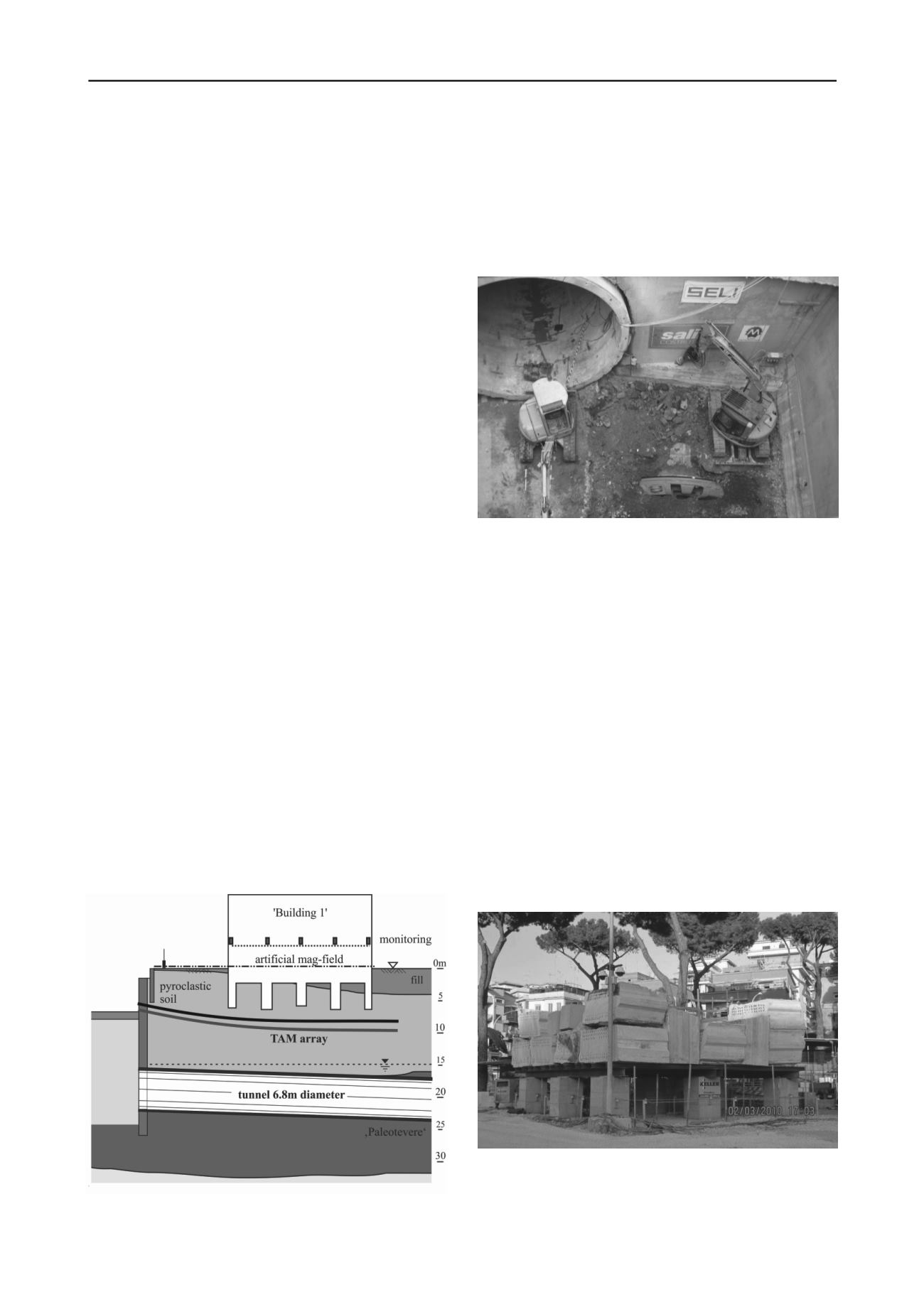
Drilling-Technology. For ‘Building 1’ the grouting pipes had a
radius of 120 to 140 m (see Fig. 3). Although the minimum
distance of the TAMs was less than 1 m from the foundation, no
significant settlement was measured during drilling.
Figure 3. Cross section of compensation grouting for ‘Building 1’.
In total, more than 100 monitoring points were installed for
controlling the compensation grouting operation with a zero
reading before any activity on site.
As all grouting parameters (e.g. TAM spacing, grout mixes,
injected volumes) were tested during the field trial, the grouting
operation was very efficient during the excavation of both
tunnels. The settlements were below the tolerable values. Fig. 4
shows both tunnels from the final station shaft.
Figure 4. Picture of finished upper tunnel and TBM in end position for
lower tunnel.
3 COMPENSATION GROUTING FOR PILED
FOUNDATIONS
Compared to the conditions of the above mentioned works with
relatively shallow foundations, circumstances were different at
‘Ionio Station’ (Kummerer et al. 2012). The tunnel diameter
was 9.8 m (double track tunnel). The grouted and excavated
soils were gravels with a low content of fines. And more
important, all buildings are founded on piles with a typical
diameter of 600 mm and a pile length of max. 19 m. Therefore
additional studies were necessary to address the very complex
situation of compensation grouting for piled foundations.
As a consequence and due to the fact that worldwide only
limited experience was available for grouting underneath piled
foundations, an additional real-scale field trial was performed.
For the trial an already excavated station was chosen
representing conditions similar to the actual compensation
grouting works. A dead load of approx. 50 kPa above 9 piles
with a length of 15 m and 20 m respectively represented the in-
situ conditions (see Fig. 5).
Figure 5. Photo of ‘Ionio Station’ full-scale field trial.
Fig. 6 shows the schematic cross section of the field trial
with ballast, piles and monitoring (liquid levels, pressure cells,
precise levelling and incremental extensometers).


